
Automatic water tank level controller motor driver circuit
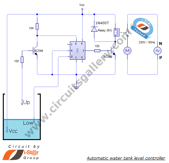
The automatic water level controller circuit operates through a simple yet effective mechanism. The NE555 timer IC serves as the central control unit, configured in a bistable mode to manage the state of the water pump based on input from the water level sensors. The two probes installed in the tank act as sensors: the top probe detects the maximum water level, while the bottom probe detects the minimum water level. When the water level falls below the bottom probe, the circuit triggers the NE555 timer, changing its output state to high, which activates the relay. This relay, in turn, powers the water pump, allowing it to fill the tank.
As the water level rises and reaches the top probe, the circuit detects this condition and resets the NE555 timer, switching the output to low and deactivating the relay, thus turning off the water pump. This automatic regulation prevents overflow and dry running of the pump, enhancing efficiency and prolonging the lifespan of the equipment.
In terms of component selection, the NE555 timer IC is favored for its reliability and ease of use. The relay should be rated appropriately to handle the motor's current, with a 32 Ampere relay being a common choice for domestic water pumps. Additional components may include resistors and capacitors for setting the timing characteristics of the NE555 timer, as well as diodes for flyback protection across the relay coil to prevent voltage spikes.
Overall, this automatic water level controller circuit is an excellent project for demonstrating basic electronic principles and practical applications in home automation, providing an efficient solution for managing water levels in tanks.Automatic water level controller circuit is a simple engineering project. It can automatically switch ON and OFF the domestic water pump set depending on the tank water level. You can implement this motor driver circuit at your home or college using less costly components. The approximated cost of the project is about $5 only. The main advantage o f this water level controller circuit is that it automatically controls the water pump without any user interaction. The heart of this pump controller circuit is a NE 555 IC; Here we have manipulated the flip flop inside the 555 timer IC.
Our project consists of two water level sensors, one fixed at the top and other at the bottom. Working of this circuit is almost similar to a bi stable mutlivibrator. Simulation of this circuit is also given below. Definitely this will help you to do your academic project. In this project 3 wires are dipped in water tank. Let us define two water levels- Bottom (Low) level and Top (Up) level. One of the wire or probe is from Vcc. When water level goes down, the 2nd pin gets disconnected(untouched) from water i. e. voltage at the trigger pin becomes less than Vcc. Then the output of 555 becomes high. For practical implementation, you must use a relay. Rating of relay is chosen according to the load (Motor). 32 Ampere relay is best suited for domestic applications. 🔗 External reference
Related Circuits

The preamplifier circuit is designed to offer appropriate loading for phono cartridges with reluctance. It achieves a gain of approximately 25 dB at 1 kHz (converting an input of 2.2 mV to an output of 100 mV). The circuit...
.jpg)
This is a general-purpose remote control project utilizing programmable PIC microcontrollers (PIC16F628, PIC16F630, PIC16F684). Schematics are provided for using infrared (IR) or radio frequency (RF) media. For those unfamiliar with microcontroller programming, fixed encoder and decoder integrated circuits can...
This article aims to utilize an old PC as a simple controller. Many outdated PCs, such as the 8088, 8086, 80286, 80386, or even 80486, have become obsolete systems. This design employs an 8-bit LPT printer parallel data port...
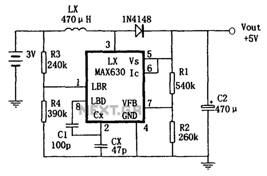
A low voltage frequency circuit utilizes the MAX630 for low battery voltage detection, functioning as an offset boost converter power supply. It is designed to maintain high efficiency (85%) while providing a DC output voltage of 5V at a...
Surround Sound Decoder circuit diagram. The circuit's operation begins when the stereo sound signal carries surround sound information through the master volume section. This drives the Left channel (Lch), which is connected to Model TL072 IC1A and IC1B, with...
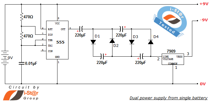
How to create a dual power supply unit using a single battery for laboratory purposes. Dual voltage power supplies are particularly needed for operational amplifier experiments and some instrumentation amplifiers. Additionally, certain low-power audio preamplifiers also require dual voltage...