
Basic circuit for PIC16F877A
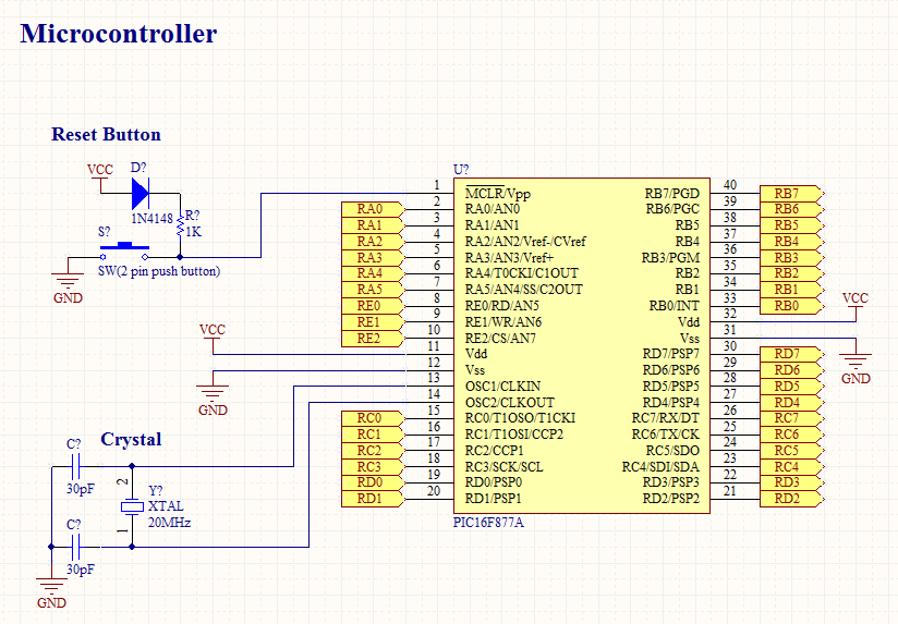
The basic circuit for operating a PIC16F877A microcontroller typically includes several essential components to ensure stable performance and reliable operation. The primary components include the microcontroller itself, a power supply, decoupling capacitors, a crystal oscillator, and input/output devices.
1. **Microcontroller**: The PIC16F877A is an 8-bit microcontroller from Microchip Technology. It features 40 pins, including digital I/O pins, analog inputs, and communication interfaces.
2. **Power Supply**: The microcontroller requires a stable power supply, typically ranging from 2.0V to 5.5V. A common choice is a 5V DC power supply. It is advisable to use a voltage regulator if the supply voltage exceeds this range.
3. **Decoupling Capacitors**: To filter out noise and stabilize the power supply, decoupling capacitors (usually 0.1µF ceramic capacitors) should be placed close to the power pins of the microcontroller. This helps prevent voltage fluctuations that could affect the operation of the microcontroller.
4. **Crystal Oscillator**: The PIC16F877A requires an external clock source for timing purposes. A crystal oscillator (commonly 4MHz or 20MHz) is often used along with two load capacitors (typically 22pF) to ensure proper oscillation frequency.
5. **Input/Output Devices**: Depending on the application, various input and output devices can be connected to the microcontroller. This may include switches, LEDs, sensors, and communication modules. Each device should be connected to the appropriate I/O pins on the microcontroller.
6. **Reset Circuit**: A reset circuit is essential for initializing the microcontroller. This can be achieved using a push-button switch connected to the MCLR pin, along with a pull-up resistor (typically 10kΩ) to ensure the pin remains high during normal operation.
7. **Programming Interface**: For programming the microcontroller, a suitable interface, such as ICSP (In-Circuit Serial Programming), should be included in the circuit. This typically involves connecting specific pins to a programmer device.
The schematic for the basic circuit will reflect these components, illustrating their interconnections and pin configurations. Proper layout and connection practices should be followed to ensure that the circuit operates efficiently and reliably.To operate a microcontroller, you need some basic components to support it and the circuit we call it basic circuit. The components needed are very common and you can find them at any electronics store out there. Here, i will share the schematic of basic circuit to operate a PIC16F877A microcontroller.. 🔗 External reference
Related Circuits
In this intercom schematic, an 8-ohm speaker is used as both a microphone and a listening speaker. A 10K potentiometer controls the volume, and the total gain can be adjusted. This intercom circuit utilizes an 8-ohm speaker in a dual...
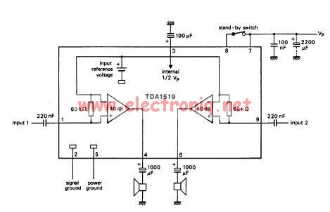
The TDA1519 circuit can deliver 2x6 watts of output power. The TDA1519 is an integrated class-B dual output amplifier housed in a 9-lead single in-line (SIL) plastic medium power package, primarily developed for car radio applications. The TDA1519 amplifier is...
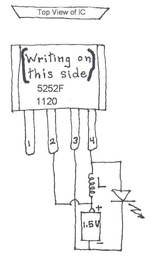
Many Joule Thief circuits traditionally rely on a bulky toroidal inductor that requires careful winding with copper wire. However, there are now compact 4-legged integrated circuits (ICs) available that can perform the same function using only a simple inductor,...
The schematic is in PDF format and cannot be sent through this site. It is recommended to check a specific website that contains various schematics, including older posts that might have the schematic needed. A WS-55807 model is experiencing...
The basic two-transistor flasher has become widely utilized in various applications due to its simplicity and versatility. It has been employed in circuits such as a micropower low battery indicator, a lightning detector, an off-line switching power supply, a...
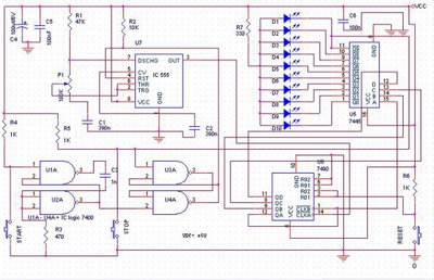
The speed test circuit is a simple design intended to measure a person's reaction time in a game. The operation of this peripheral is straightforward, facilitated by several integrated circuits, including a counter, timer IC, and decoder. The timer...