
Intercom Circuit

This intercom circuit utilizes an 8-ohm speaker in a dual role, functioning as both the input (microphone) and output (listening speaker) device. The design leverages the inherent properties of the speaker to convert sound waves into electrical signals and vice versa. The 10K potentiometer serves as a variable resistor, allowing the user to adjust the volume level of the audio output.
In the schematic, the speaker is connected in parallel with a preamplifier stage, which is essential for boosting the weak audio signals captured by the speaker when used as a microphone. The output of this preamplifier is then fed into an operational amplifier (op-amp) circuit, which further enhances the signal strength. The gain of the op-amp can be adjusted using feedback resistors, allowing for fine-tuning of the audio levels.
The 10K potentiometer is strategically placed in the circuit to provide a user-friendly interface for volume control. By varying the resistance of the potentiometer, the signal level sent to the output stage can be increased or decreased, enabling the user to achieve the desired listening volume without introducing significant distortion.
Power supply considerations are also crucial in this design. The circuit typically requires a DC power source, which can be derived from batteries or a wall adapter. Proper decoupling capacitors should be included to filter out any noise from the power supply, ensuring clean audio performance.
Overall, this intercom schematic presents a simple yet effective design for audio communication, utilizing common components to achieve functionality and ease of use. The dual-purpose speaker and adjustable gain through the potentiometer make it an efficient solution for basic intercom applications.In this intercom schematic, the 8 ohm speakers is used as microphone and listening speaker. The 10K potentiometer controls volume and the total gain can be.. 🔗 External reference
Related Circuits
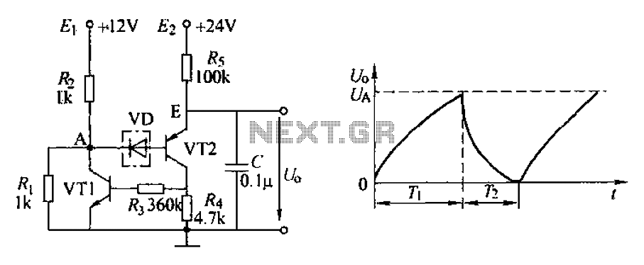
The application circuit depicted is a complementary sawtooth generator. In the schematic, VT1 is the transistor with a base current limiting resistor, which prevents excessive base current flow through the crystal tube. The resistor R4 acts as a bleeder...
Crystal Y1 generates a fundamental frequency clock signal of 14.31818 MHz. U31 is a Dual Voltage Controlled Oscillator (VCO) that produces a 14.31818 MHz clock signal, referred to as the color clock, at pin 10. The output frequency can...
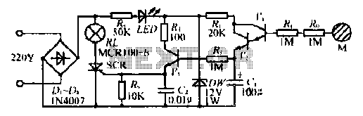
The circuit operates without a base current for the transistor. It turns off when the metal sheet is touched, causing the capacitor to start charging. The capacitor charges to 2V over a specified time. The circuit generates a conduction...
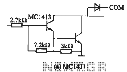
The MC1411 series is a Darlington driver with a compact, reliable internal structure. It is particularly suited for high-voltage applications, functioning effectively as a high-voltage peripheral driver. This driver can directly control relays, lights, and other loads. It is...
The 3F155 circuit, as depicted in the provided figure, operates in manual control mode. It features a self-excitation braking phase, while the other two phases utilize a short brake. A resistor (R) is involved, along with the voltage across...
The figure illustrates a schematic circuit of a UV sensor. When voltage is applied between the cathode and anode, and UV radiation passes through the quartz glass tube on the cathode's optical surface, the cathode material, which is coated...