
Crystal Oscillator Design
The crystal oscillator circuit utilizes a quartz crystal resonator to generate a stable frequency output. The primary components typically include the crystal, an amplifier (often a transistor or operational amplifier), and feedback components such as resistors and capacitors. In this specific circuit, the 3.5 MHz crystal serves as the frequency-determining element, ensuring that the oscillator maintains a consistent output frequency with minimal drift.
The circuit configuration can vary, but a common design involves the crystal connected in a feedback loop with an amplifier. The amplifier boosts the signal generated by the crystal, while the feedback network ensures that the output remains in phase with the input, thus sustaining oscillation. The stability of the output frequency is primarily influenced by the characteristics of the crystal, including its cut, temperature stability, and load capacitance.
In practical applications, crystal oscillators are widely used in clocks, timers, and frequency synthesis, where precise timing is crucial. The output waveform is typically a square wave, which may require further conditioning, such as filtering or shaping, depending on the intended application. Proper layout and component selection are essential to minimize noise and ensure reliable operation at the specified frequency.HI, i Just wanted to understand this circuit better and discuss with people So here it is a ,crystal oscillator It uses a 3.5Mhz Crystal and.. 🔗 External reference
Related Circuits

This Wien bridge oscillator utilizes an incandescent lamp to stabilize its amplitude. The amplitude stabilization results in a low distortion output and supports multiple frequencies. The Wien bridge oscillator is a type of electronic oscillator that generates sine waves. It...
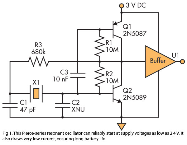
A Pierce (crystal) oscillator designed to deliver a stable clock signal for a minimum duration of one year when powered by battery voltages as low as 2.4 V. The Pierce oscillator circuit is a type of crystal oscillator that utilizes...
This is a brief guide to help users begin with KiCAD. The tutorial focuses on a simple astable multivibrator circuit utilizing the 555 timer IC. The astable multivibrator circuit using the 555 timer IC is a fundamental electronic configuration that...

Adding a diode, a resistor, and a capacitor to the surface-acoustic-wave (SAW) oscillator enables its use in frequency-shift-keying (FSK) applications. The diode (D1), resistor (R1), and capacitor (C1) create a simple diode switch where D1 shunts C1 to ground....

This smoke detector electronic project is designed using the LM1801 and common electronic components. The smoke detector circuit diagram does not utilize ionization detection, gas sensors, or optocouplers; instead, it employs two photoresistors (LDRs) and an LED. The circuit...

The circuit was designed to produce a preamplifier with symmetrical audio input while the output operates in Class A type. Preamplifier (pre-amp) a device... The circuit in question is a preamplifier designed to handle symmetrical audio inputs, which ensures that...