
Class A-Designed Symmetrical Audio Preamplifier
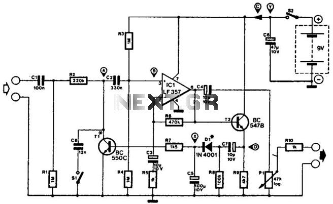
The circuit in question is a preamplifier designed to handle symmetrical audio inputs, which ensures that both positive and negative halves of the audio signal are amplified equally. This is particularly important in audio applications where signal integrity and fidelity are paramount. The output stage of this preamplifier operates in Class A mode, known for its high linearity and low distortion characteristics, making it ideal for high-quality audio amplification.
The schematic typically includes several key components: operational amplifiers (op-amps) for signal amplification, resistors for setting gain and biasing, capacitors for coupling and decoupling, and possibly a power supply section to provide the necessary voltage levels for the op-amps. The symmetrical input configuration may utilize differential input stages to reject common-mode noise, which is beneficial in maintaining audio quality.
In Class A operation, the output transistors conduct over the entire cycle of the input signal, resulting in a linear response that minimizes crossover distortion. This is achieved by biasing the transistors so that they remain in the active region at all times. The trade-off for this linearity is decreased efficiency, as Class A amplifiers tend to dissipate more power as heat.
Overall, the design emphasizes high fidelity and low distortion, making it suitable for high-end audio applications, such as in professional audio equipment or high-quality home audio systems. Proper thermal management and careful component selection are critical to ensure optimal performance and reliability of the preamplifier circuit.The circuit was designed to produce a preamplifier with symmetrical audio input while the output operates in Class A type. Preamplifier (pre-amp) a devi.. 🔗 External reference
Related Circuits
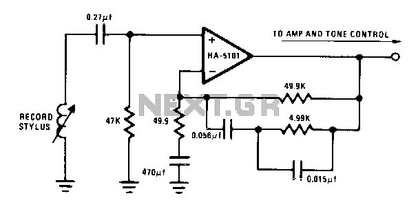
The circuit provides low-frequency boost below 318 Hz and high-frequency attenuation above 3150 Hz. Recent modifications to the response standard include a 31.5-Hz peak gain region to reduce de-oriented distortion from external vibration. The described circuit functions as an audio...
This compressor will compress a 25-mV peak-to-peak (p-p) audio signal to a 20-V p-p output, maintaining input levels between 1.5 V p-p and 3.5 V p-p, with a frequency response ranging from 7 Hz to 67 kHz. It is...
Where can one obtain a 12AX7 tube? These tubes are very popular for use in the preamplifier stages of many professional electric guitar amplifiers. A good music store will have them available for a modest price (around $12 US...
Blue VALUES replaced by values in RED. Blue COMPONENTS removed from circuit. Red components added to circuit. In this circuit modification, the original design underwent significant changes where blue values were substituted with corresponding red values to enhance performance or...
Adding this combination audio circuit, as illustrated in figure 14-38, to the automatic rhythm generator of electronic musical instruments fulfills the players' demand for incorporating drum and cymbal audio, enhancing the overall performance effect. The diagram indicates that the...
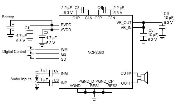
The NCP2830 audio power amplifier features high-quality audio performance with a total harmonic distortion plus noise (THD+N) of 0.04%. It offers low noise with a signal-to-noise ratio (SNR) of up to 100 dB and optimizes overall system efficiency, achieving...
Warning: include(partials/cookie-banner.php): Failed to open stream: Permission denied in /var/www/html/nextgr/view-circuit.php on line 713
Warning: include(): Failed opening 'partials/cookie-banner.php' for inclusion (include_path='.:/usr/share/php') in /var/www/html/nextgr/view-circuit.php on line 713