
Crystal Tester Circuit

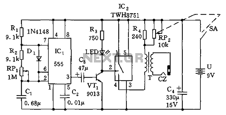
The circuit operates on a straightforward principle of oscillation. The heart of this tester is the crystal oscillator formed by the combination of the crystal and transistor T1. When a functional crystal is connected, it resonates at its specified frequency, leading to oscillation. Capacitors C1 and C2 are critical for ensuring that the oscillation is stable and can be effectively measured. They create a voltage divider that allows a portion of the oscillating signal to be fed back to the transistor, maintaining the oscillation.
The output of the oscillator is a sine wave, which is then processed by the rectifier circuit composed of diodes D1 and D2. This rectification converts the AC signal into a pulsating DC signal, which is further smoothed by capacitor C4. This filtering is essential for providing a stable DC voltage to the base of transistor T2. The base-emitter junction of T2 acts as a switch; when the voltage exceeds a certain threshold, T2 turns on, allowing current to flow through the LED, thus illuminating it.
In summary, this crystal tester circuit offers an efficient and cost-effective solution for hobbyists and engineers alike to test oscillator crystals quickly and accurately. Its design leverages basic electronic components to achieve functionality that rivals more expensive commercial alternatives. The simplicity of the circuit allows for easy assembly and troubleshooting, making it an ideal project for those looking to enhance their understanding of oscillator circuits and crystal technology.The idea for this crystal tester circuit sprung out of the need of testing a large number of oscillator crystals lying unused in a big hobby box. testing the crystals one by one without the appropriate device would have been very slow and a time consuming task.
Commercial crystal testers are however very expensive, that is why this simple electron ic crystal tester was born. The transistor T1 and the crystal to be tested together makes a complete crystal oscillator. The capacitors C1 and C2 works as a capacitive voltage divider that is connected to the transistor T1. If the crystal being tested is intact, the circuit oscillates. The sine wave oscillation voltage is fed to the rectifier circuit (d1, D2) and filtered by capacitor C4.
With an intact crystal, the DC voltage at the base of the transistor T2 is high enough to cause the transistor to conduct. The LED lights up signalling that the crystal is good. 🔗 External reference
Related Circuits
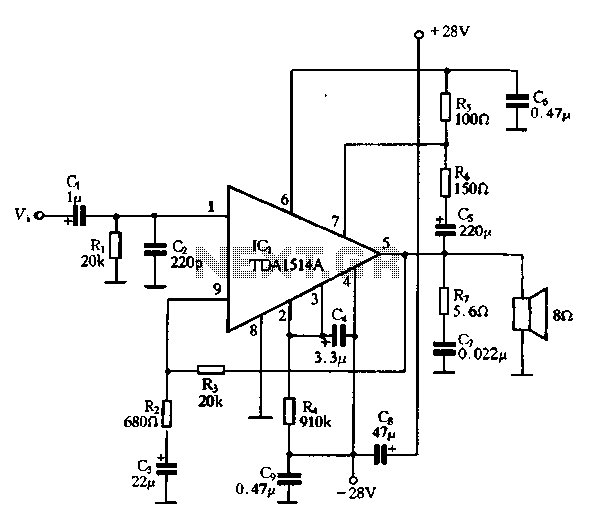
The typical application circuit for the TDA1514A includes resistors R2 and R3, which form a feedback circuit to adjust their ratio, thereby creating an adjustable circuit loop gain. To enhance the dynamic range of the circuit, capacitors C5 and...
A voltage supply ranging from 6 V to 15 V is required when using a single LED per module. An increase in the number of LEDs necessitates a corresponding increase in the voltage supply, with additional LEDs connected in...
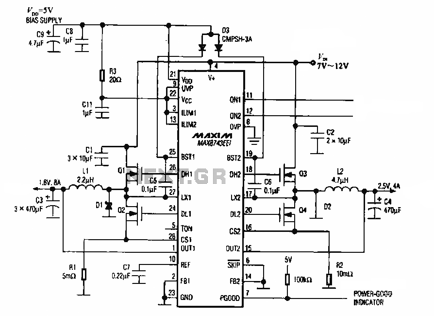
The circuit utilizes the MAX8743 chip for a laptop chipset power supply. It demonstrates the conversion of a 5V power supply into +2.5V and +1.8V outputs. The MAX8743 is a highly integrated power management solution designed specifically for laptop chipsets....
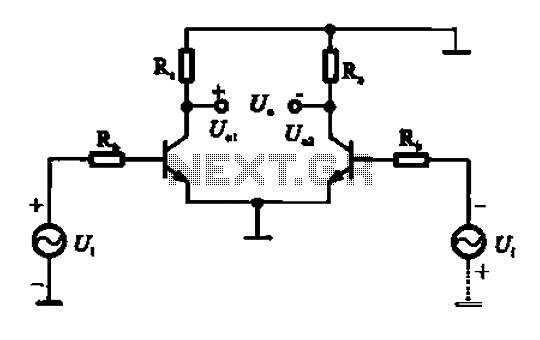
An amplifier circuit is designed to handle an assumed input consisting of two equal and opposite polarity signals, known as a differential mode signal. The two tube collector currents, Ic and IC7, are balanced in such a way that...
The circuit is composed of a 555 oscillator and an amplifier driver stage. It includes the 555 timer along with resistors R1, R2, RP1, capacitor C1, and other components forming a multi-harmonic oscillator. The frequency can be adjusted using...
This small transistor tester employs a simple visual indication system to perform a quick go/no-go check on both NPN and PNP transistors. If the tested device is a functional NPN transistor, the green LED (D1) will flash, while the...