
Amplifier circuit equivalent

The described amplifier circuit operates on the principle of differential mode signaling, which is essential in various applications such as operational amplifiers and audio amplifiers. The circuit utilizes two active devices, such as transistors or vacuum tubes, arranged in a way that their outputs are inversely related. This arrangement allows for the enhancement of the desired signal while simultaneously rejecting common-mode noise, which is noise that appears equally on both inputs.
In this circuit, the collector currents Ic and IC7 are critical parameters that dictate the performance of the amplifier. By maintaining a balance between these currents, the circuit ensures that the differential mode signals are amplified effectively without the influence of negative feedback mechanisms that could distort the output. The resistor Re plays a pivotal role in stabilizing the operating point of the amplifier. When the current through Re is zero, it indicates that the circuit is optimally configured for differential mode operation, allowing the amplifier to respond linearly to input variations.
Furthermore, the design of the amplifier must consider the frequency response, gain characteristics, and power supply requirements to ensure that it meets the desired specifications for its intended application. The absence of negative feedback in this configuration is particularly advantageous for high-fidelity applications where signal integrity is paramount. Overall, the amplifier circuit described is a fundamental building block in electronic design, showcasing the principles of differential amplification and current balancing.Amplifier circuit equivalent O assumed input of the circuit plus two equal and opposite polarity signals (differential mode signal). The two tube collector current Ic, and IC7 equal and opposite, namely to increase the number of South I, IC2 is necessary to reduce the number. Thus the current flowing through the change amount of Re is zero (i.e. Ue 0, which is adjacent to no effect on the presence of differential mode signals, i.e., no negative feedback), does not affect the differential mode amplification. Therefore, the differential-mode signal words,
Related Circuits
This is an intercom circuit that utilizes the LM380 as the audio amplifier and two transistors for the microphone preamplifier. The sound quality is sufficiently good while maintaining a low construction cost. The circuit comprises two identical intercom units,...
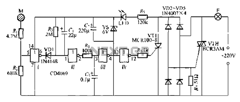
The CD4069 is a digital integrated circuit that utilizes boron to delay the activation of a light touch. It employs a j-wire connection force method and can directly replace a standard light switch without requiring changes to the existing...

The schematic for this project is not overly complex; however, it is crucial to understand the circuit board and its operation due to the high voltages generated. Below is a rough draft schematic of the camera used for this...
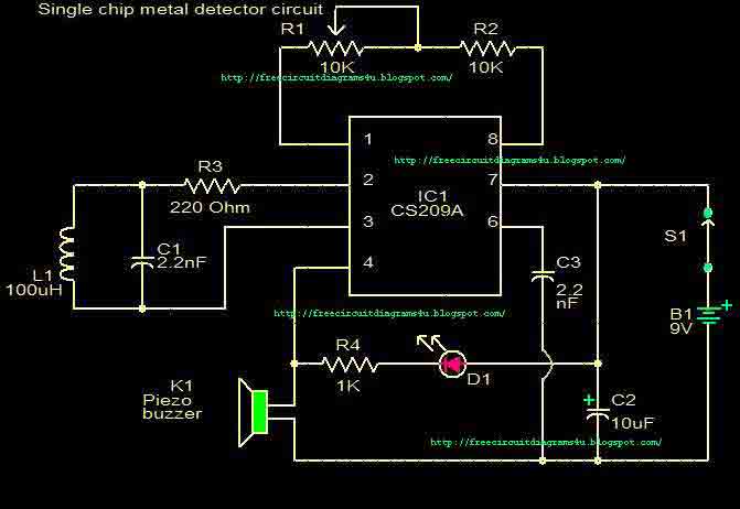
This circuit is a single chip metal detector. Actually, we can use this one to detect metals. Especially, you have seen some army soldiers keep something to detect metals. That equipment has been made through this circuit. So you...
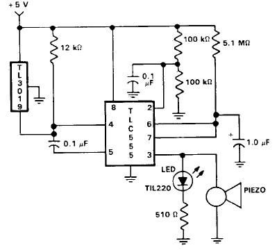
This door open alarm electronic project is designed using a linear hall effect device and a 555 timer circuit. The project utilizes the TL3103 linear hall effect device for detecting the angle of rotation. The TL3103 is positioned within...
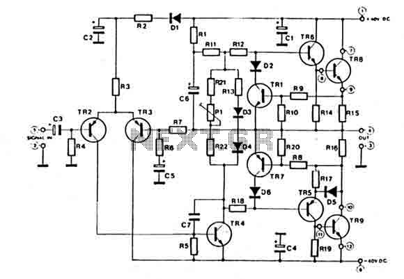
This amplifier features a high-quality circuit equipped with complete short circuit protection and exhibits very low total harmonic distortion (T.H.D.) across a full range of frequencies. It requires a symmetrical power supply of ±40V. The output power transistors are...