
Digital-to-analog converter (DAC)
")
In the context of electronic circuit design, a digital-to-analog converter (DAC) plays a crucial role in bridging the digital world with the analog domain. The conversion process typically involves interpreting binary input values and translating them into corresponding voltage or current outputs. The use of Pulse Width Modulation (PWM) as a method for DAC implementation is particularly advantageous due to its simplicity and efficiency. PWM operates by varying the width of the pulses in a signal, which allows for precise control over the average voltage delivered to the load.
The duty cycle of a PWM signal is a critical parameter that defines the ratio of the time the signal is high (on) to the total period of the signal. For instance, a PWM signal with a 50% duty cycle will have equal time spent in the high and low states, effectively averaging out to half the supply voltage at the output. This characteristic makes PWM an effective method for generating analog signals from digital inputs, as it allows for the easy adjustment of output levels by modifying the duty cycle.
In practical applications, the DLN-series PC-I2C/SPI/GPIO Adapters provide a versatile platform for controlling DACs. These adapters enable users to interface with various types of DACs using standard communication protocols such as I2C or SPI, facilitating the integration of digital control with analog output. The availability of both high-frequency and low-frequency PWM controllers within these adapters enhances their utility, allowing for optimal performance across different applications. High-frequency PWM is particularly beneficial for DAC control as it minimizes the ripple in the output signal, resulting in smoother and more accurate analog outputs.
In summary, the combination of digital-to-analog conversion through PWM, along with the capabilities provided by the DLN-series adapters, allows for the effective generation of analog signals from digital sources, making it an essential component in modern electronic systems.In electronics, a digital-to-analog converter (DAC or D-to-A) is a device for converting a digital (usually binary) code to an analog signal (current, voltage or electric charge). You can use DAC for testing circuits and amplifiers or for generating the high complexity signals. Digital to analog converter can be easily implemented with Pulse Width Modulation (PWM). On the following figure you can see three PWM signals with different duty cycles. The duty cycle describes the proportion of positive pulse width to the period. PWM waveforms with 33%, 50% and 75% of duty cycle are shown below. These three PWM signals can be converted to three different analog values, at 33%, 50%, and 75% of the full strength. For instance, when the voltage level is 5V and the duty cycle is 50%, digital to analog converter outputs 2.
5V. You can use PWM interface of DLN-series PC-I2C/SPI/GPIO Adapters to implement wide variety of digital to analog converters. These converters can be easily controlled from PC SW. DLN-series USB-I2C/SPI/GPIO adapters has both high-frequency and low-frequency PWM controllers. The high-frequency PWM (HPWM) suits better for DAC controlling. 🔗 External reference
Related Circuits
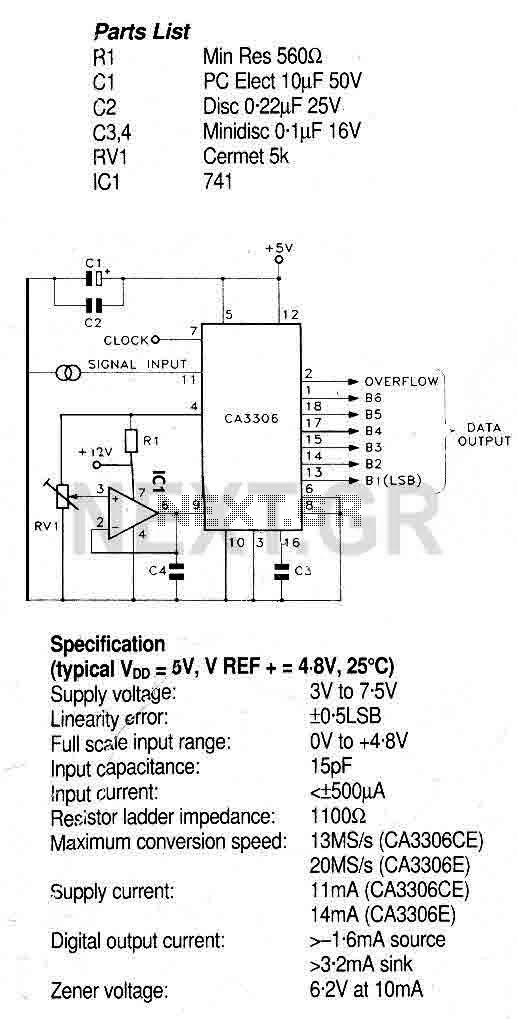
This circuit utilizes the CA3306, a family of CMOS parallel (flash) analog-to-digital converters designed for low power and high-speed applications. The CA3306CE operates at sampling rates of up to 10 million samples per second, while the CA3306E can achieve...
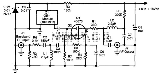
This converter utilizes a 40673 MOSFET to heterodyne the 5.5 to 8 MHz TVRO subcarriers to the FM broadcast band, enabling the use of a stereo receiver for high-fidelity stereo reception of TV sound subcarriers. Z1 is a prepackaged...
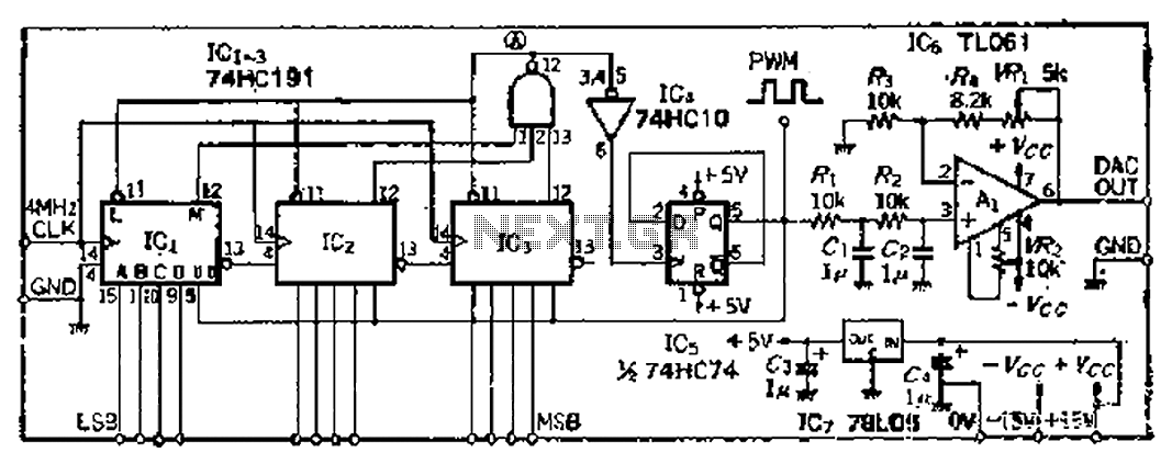
A PWM clock signal is generated at 4096 times the input frequency, counting up (Q3) until the base of ICi-IC3 is full. The output point produces a maximum clock signal. On one side, voltage data is loaded into IC3,...
The designer requires a 1-Wire host computer IO framework that operates at 1.8V. Most 1-Wire devices are unable to function at this voltage. This application recommends implementing a 1.8V 1-Wire host computer alongside a 5V 1-Wire reference design for...
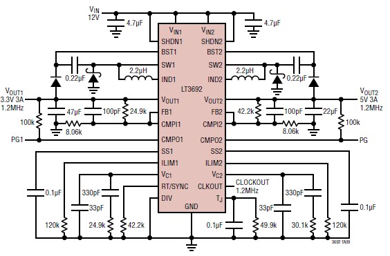
A 3.3V and 5V DC-DC converter circuit design project utilizing the LT3692 dual tracking regulator. The LT3692 is a highly efficient dual-output DC-DC converter designed for applications requiring both 3.3V and 5V outputs. This integrated circuit can provide a regulated...
A 555 timer can be used to generate a square wave to produce a negative voltage relative to the negative battery terminal. When the timer output at pin 3 goes positive, the series 22 uF capacitor charges through the...