
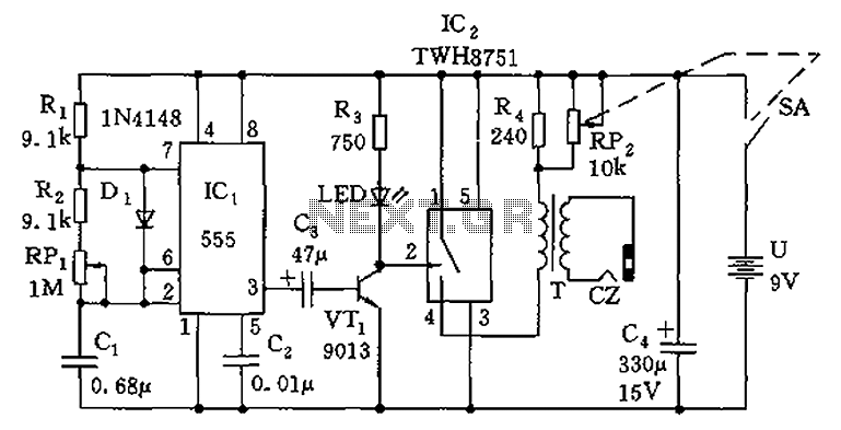
9V to 5V converter schematic with 555

The circuit utilizes a 555 timer configured in astable mode to generate a square wave output. The output from pin 3 of the 555 timer alternates between high and low states, which is instrumental in charging and discharging the capacitors involved in the circuit. Initially, when the output is high, the 22 µF capacitor (C1) charges through diode D1, allowing it to reach approximately 8 volts. This charging phase is critical for establishing the necessary potential difference for generating the negative voltage.
When the output switches to a low state, the 22 µF capacitor discharges through diode D2. This action allows the capacitor to transfer its stored energy to the 100 µF capacitor (C2), creating a negative voltage relative to the negative terminal of the battery. The circuit is designed to allow the negative voltage to accumulate over several cycles, potentially reaching around -7 volts. However, this negative voltage is regulated by a 5.1-volt zener diode (Z1), which prevents the voltage from exceeding safe levels.
The overall current consumption of the circuit is approximately 6 milliamps when the zener diode is not connected. With the zener diode in place, the current draw increases to about 18 milliamps. The output current available for driving a load is around 12 milliamps, indicating that the circuit is capable of powering small devices or components.
For applications requiring a symmetrical power supply, an additional 5.1-volt zener diode and a 330-ohm resistor can be integrated into the circuit. This configuration would allow regulation of the +9 volts down to +5 volts at 12 milliamps, thereby providing a dual supply of +5 volts and -5 volts. The inclusion of this additional regulation would increase the battery drain to approximately 30 milliamps, necessitating consideration of battery capacity and longevity in the design of the overall system.A 555 timer can be used to generate a squarewave to produce a negative voltage relative to the negative battery terminal. When the timer output at pin 3 goes positive, the series 22 uF capacitor charges through the diode (D1) to about 8 volts.
When the output switches to ground, the 22 uF cap discharges through the second diode (D2) and charges the 100 uF capacitor to a negative voltage. The negative voltage can rise over several cycles to about -7 volts but is limited by the 5.1 volt zener diode which serves as a regulator.
Circuit draws about 6 milliamps from the battery without the zener diode connected and about 18 milliamps connected. Output current available for the load is about 12 milliamps. An additional 5.1 volt zener and 330 ohm resistor could be used to regulate the +9 down to +5 at 12 mA if a symmetrical +/- 5 volt supply is needed.
The battery drain would then be around 30 mA. 🔗 External reference
Related Circuits
The original coil that came with the Heathkit project was preassembled at the factory. It had a diameter of around 15 cm (6 inches). A larger (30 cm, 12 inches) coil can be made using the following data. The design...
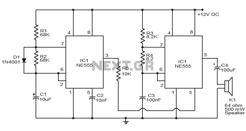
Numerous electronic circuits utilizing the NE555 timer IC have been published, and this is yet another example. The circuit diagram presented illustrates a police siren based on the NE555 timer IC. It employs two NE555 timer ICs, each configured...
The circuit has been designed for telephone apparatus to indicate an incoming call as it rings using an LED for visual indication. BC550, an NPN general-purpose transistor, is utilized in the design. The circuit operates by detecting the ringing voltage...
To provide rapid motor speed changes and motor direction reversal, four outputs drive a MOSFET H-bridge. N-channel devices serve as the lower rail power MOSFETs, while P-channel devices are utilized as the upper MOSFETs. All MOSFETs are controlled by...
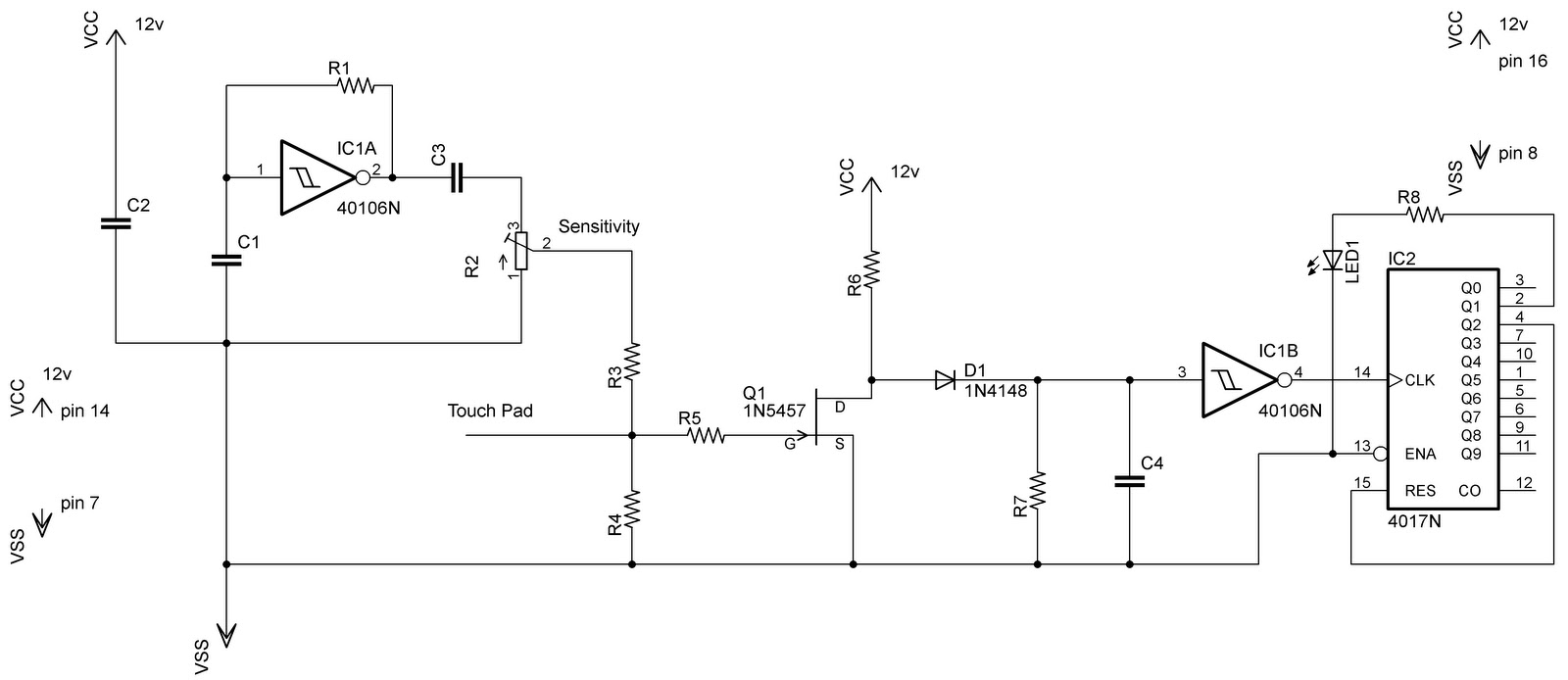
In the previous post regarding a capacitive touch switch, the output was activated only while the touch was maintained. This means that the circuit would drive the load only during the touch, and once the touch was removed, it...
The circuit is composed of a 555 oscillator and an amplifier driver stage. It includes the 555 timer along with resistors R1, R2, RP1, capacitor C1, and other components forming a multi-harmonic oscillator. The frequency can be adjusted using...