
Electronic robot wiring schematic
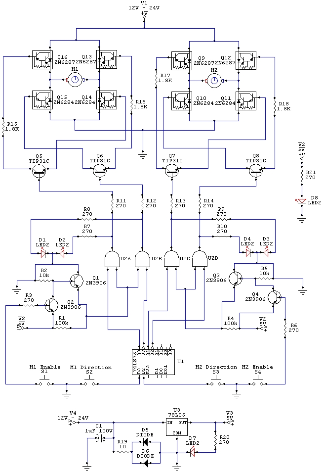
The wiring schematic serves as a crucial element in the design and operation of the robot, illustrating the interconnections between various components that facilitate movement. The diagram includes representations of the motors, microcontrollers, power supply, and the necessary connections that allow for the control signals to be transmitted effectively.
In this schematic, the motors are typically represented by their symbols, which indicate their type—such as DC motors or stepper motors—along with their rated voltage and current specifications. The microcontroller, which acts as the brain of the robot, is depicted with its pin configurations clearly labeled to show how it interfaces with the motors. Control signals from the microcontroller dictate the direction and speed of the motors, enabling precise movements.
Power supply connections are also illustrated, highlighting the voltage levels required for both the microcontroller and the motors. This ensures that all components receive the appropriate power without risk of damage. Additionally, any sensors that may be included in the design, such as distance sensors or gyroscopes, are marked on the schematic, showing how they connect to the microcontroller for feedback on the robot's position and orientation.
The use of Circuit Maker 2000 for designing this schematic allows for a clear and organized layout, making it easy for engineers to understand the relationships between components and troubleshoot any issues that may arise during the robot's operation. Proper labeling and color-coding of wires can further enhance readability, ensuring that the schematic serves as an effective reference throughout the development and testing phases of the robot.The wiring schematic played a big roll on the robot. This diagram is used to graphically display all the wiring of the motor controlling micro-components that gave the robot the ability to physically move forward, backward, left, right, and stop. (This diagram was designed in Circuit Maker 2000) 🔗 External reference
Related Circuits
Nissan Sentra 1.6 Liter Manual Transmission Starter Circuit Wiring Diagram. The Nissan Sentra 1.6 Liter manual transmission starter circuit wiring diagram provides a visual representation of the electrical connections involved in the starting system of the vehicle. This diagram is...
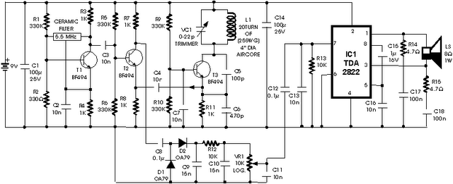
The Jammer is a very small circuit and can fit inside a small plastic box with 9V battery inside. It can be very illegal if you attach an external antenna so don't. adjust frequency by turning trimmer. It is...
PCM Powercom was established in 1987 and is a prominent provider of power protection products, holding an ISO 9001 certification. The company employs more than 2,600 individuals globally. PCM Powercom specializes in the design and manufacture of power protection solutions,...
The metal detector circuit is presented here, illustrating a simple yet effective design. It utilizes a 40, 106 Hex Schmitt inverter IC, a capacitor, a search coil, and batteries. An advantage of connecting IC1b Pin 4 to a medium-wave...

The thermostat electric circuit operates as depicted in the figure. It has three settings: off, low power (Lo), and high power (Peru HL). When the DIP switch SA is set to the Lo position, 220V AC is directed through...
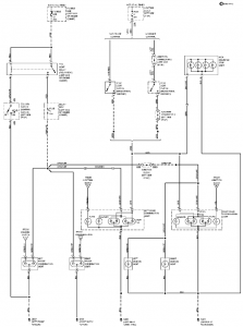
The connection and wiring between each part and component of the exterior lighting system of the vehicle includes elements such as the fusible link, junction block, tail light relay, cruise control, stop light switch, relay box, column switch, rear...