
HD44780 Character LCD Displays Tutorial
The HD44780 compatible display is a widely used component in electronic projects due to its ease of interfacing and versatility. The use of DIP switches in this setup allows for manual input of commands without the need for a microcontroller, making it an excellent educational tool for understanding the operation of LCD displays. The ST7065C controller, which is compatible with the HD44780, facilitates standard command sets and data handling protocols, ensuring that users can easily implement text and graphical displays.
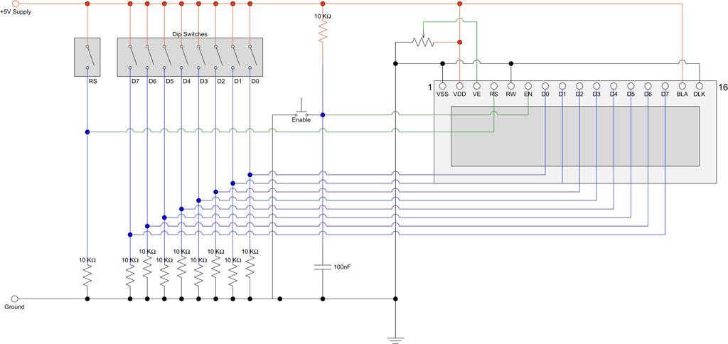
In this configuration, the 10K pull-down resistors on the RS and data lines ensure that the display remains in a known state until the switches are activated. This prevents any unintended commands from being sent to the display. The enable line's high-to-low transition is critical for the display to process the incoming data or commands; thus, the debouncing capacitor is essential for ensuring that a single press of the button results in a clean transition without noise that could cause multiple triggers.
The 4-bit interface mode is particularly beneficial in applications where pin count is limited, allowing for the same functionality with fewer connections. This mode requires two sequential writes of 4 bits each, which can be managed by toggling the RS line appropriately and ensuring that the enable line is activated after each nibble. This flexibility makes the HD44780 display suitable for a variety of microcontroller applications, where resource optimization is essential.
Overall, this circuit exemplifies the fundamental principles of interfacing with an LCD display and provides a clear demonstration of how to manipulate the display using basic electronic components, catering to both educational purposes and practical applications in embedded systems.Interfacing with a HD44780 compatible display using some DIP switches and a few other components. The module that we are using is a 16 character x 2 line display that we stock over here. It uses an ST7065C controller, which is HD44780 compatible. The figure below shows the LCD module and pinout. The circuit diagram below shows the LCD module with the basic plumbing wired up. You will notice that pin 5 (RW) is tied to ground. This pin is use to control whether you are reading or writing to the display. Since reading from the display is very rare, most people just tie this pin to ground. Data and commands are sent to the module using the 8 data lines (pins 7-14) and the RS line (pin 4). The RS lines tells the module whether the 8 data bits relate to data or a command. The data/command is read on the falling edge of the enable line (pin 6). This means that when enable transitions from high to low, the values of D0 to D7 and RS are read. There are minimum wait times between these operations, but I won`t go into them here. You can look these up in the LCD Module Datasheet. (look at the timing diagrams on page 4) HD44780 based display modules also have a 4 bit interface mode. Under this mode the data or command is transferred to the module using 2, 4 bit nibbles. This will be discussed in more detail below. Normally you would drive an LCD display from a microcontroller, computer or similar device. For this exercise we will use just a series of switches. This cuts the interface to the absolute bare essentials. The photo below shows the circuit, on a breadboard without the LCD module. I`ve also added a small L7805 based power supply on the right hand side of the board. You can get the parts for the power supply here. The Register Select and data lines are pulled down using a 10K resistor and when the dip switch is closed, those lines go high.
The enable line on the other hand is pulled high and when the button is pressed, the line goes to ground. The enable button has a 10nF capacitor to de-bounce it. Next we insert the LCD module into the breadboard and power it on. When you insert the module into the breadboard, you need to be gentle and work the pins in slowly because the pins are a bit thicker than you would normally use with a breadboard.
If you don`t see the pattern shown below, you will need to turn the contrast pot till you do. This pattern is the default pattern for an uninitialized LCD display. So to output the text Hello World we need to power up the device then enter the following sequence of Data/Commands, pressing Enable at the end of each Data/Command block. 🔗 External reference
Related Circuits
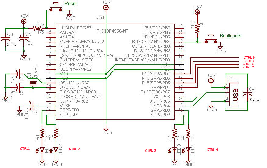
This project demonstrates a computer control interface using a USB board (USB Interface Project). This tutorial provides a straightforward method to control devices such as LEDs, motors, and other components via a computer using a USB board. Traditionally, devices...

An 8051 program must interact with external devices that facilitate communication with users. One of the most prevalent devices connected to an 8051 microcontroller is an LCD display. Common types of LCDs used with the 8051 include 16x2 and...
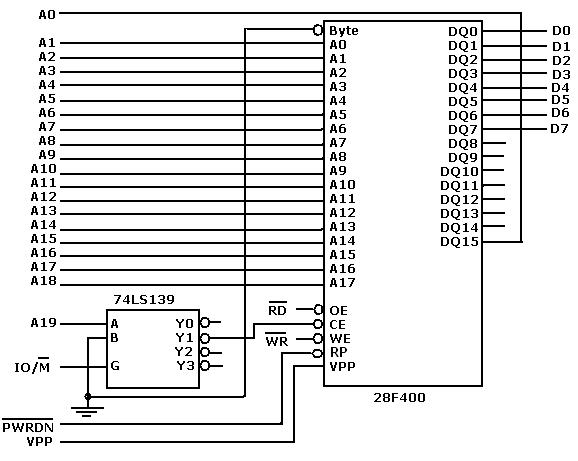
Flash memory, also known as flash RAM, is a type of non-volatile semiconductor memory device that retains stored data even when not powered. It is an enhanced version of electrically erasable programmable read-only memory (EEPROM). The primary distinction between...
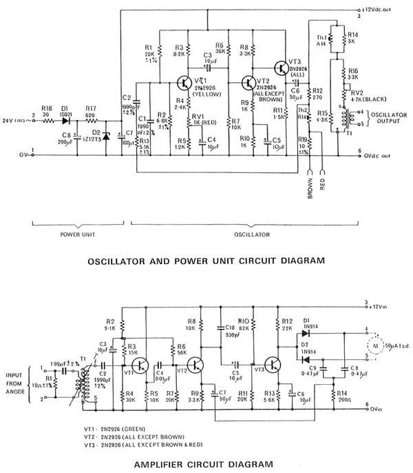
The AVO VCM 163 is a tube tester capable of measuring tube electrode currents, such as plate and screen currents, as well as mutual conductance simultaneously. It is the most advanced tube tester developed by AVO. The voltages applied...
The enable signal for the USB chip and GLCD controller is generated by a PLD decoder from the address lines. The memory map for the I/O of the 8051SBC board indicates that the available space ranges from 0x0300 to...
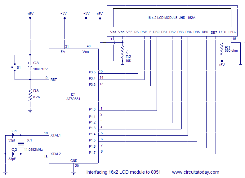
Interfacing a 16x2 alphanumeric LCD module with the AT89S51 microcontroller. The circuit diagram, theory, and program are included. JHD162 LCD module pinout and commands are provided. The integration of a 16x2 alphanumeric LCD module with the AT89S51 microcontroller involves several...