
Infrared (IR) Sensor/DetectorCircuit using 555 IC
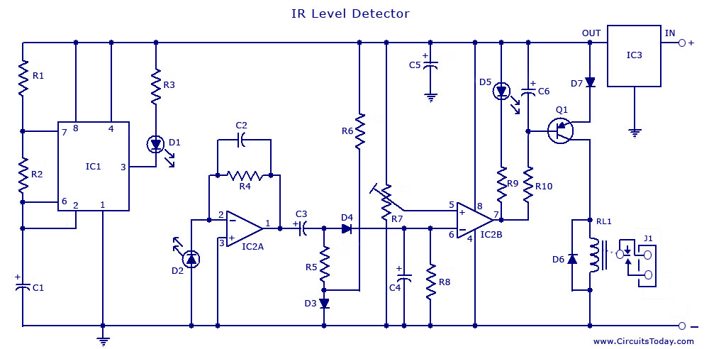
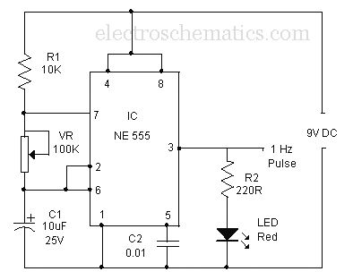
The described circuit employs a 555 timer IC configured in a monostable or astable mode to facilitate the detection of infrared signals. The IR sensor consists of an IR LED and a photodiode or phototransistor. The IR LED emits infrared light, which is reflected back to the photodiode or phototransistor when an object, such as a liquid surface, is present within the detection range.
In the water level sensing application, the circuit is designed to detect the presence of water by measuring the change in the infrared light reflected back to the photodetector. When the water level rises to a certain point, the reflected IR light intensity increases, triggering the 555 timer to output a high signal. This output can then be used to activate an indicator, such as an LED or a relay, to signal that the water level has reached a desired threshold.
For proximity detection, the circuit can be adjusted to sense the presence of nearby objects without physical contact. The distance at which the IR sensor operates can be modified by changing the values of the resistors and capacitors in the circuit. The output of the 555 timer can be configured to drive other components, such as alarms or automated systems, based on the proximity of the detected object.
Overall, this IR sensor circuit using a 555 IC is versatile and can be adapted for various applications, including liquid level monitoring and object detection, making it a valuable component in electronic projects.An Infrared or IR sensor/detector circuit diagram using 555 IC used mainly as Water level or Liquid level sensor and proximity detector circuit.. 🔗 External reference
Related Circuits
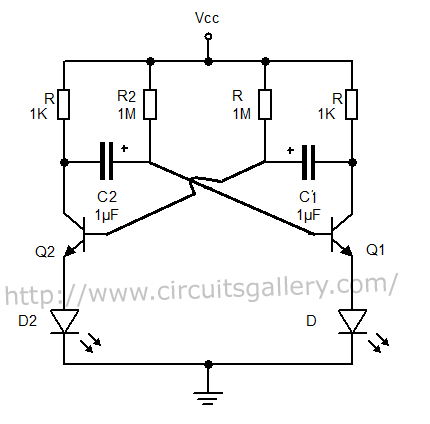
The output can also be taken from the collector terminals of the transistors, as illustrated in the circuit below. To understand the operation of the circuit, it is recommended to read about how a transistor functions as a switch. In...
The schematic for an infrared burglar alarm circuit is depicted in Figure 1. The infrared transmitter operates as a multivibrator with an oscillation frequency of 40 kHz, utilizing the NE555 integrated circuit (IC2), along with resistors R1 and R2...
The most common application for the NTC thermistor is temperature measurement. Accurate temperature measurement can easily be accomplished by interfacing a Wheatstone Bridge, 6K/30K ohm thermistor network and a digital voltmeter integrated circuit as illustrated in Figure 5. The...
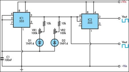
This timer utilizes two 555 integrated circuits (ICs) to adjust the desired output. The variable resistors VR1 and VR2 serve as potentiometers to modify the cycle speed. The circuit can be powered with a 9 to 12-volt power supply,...

Figure 3 illustrates a circuit featuring the OP37, which is a multi-preamplifier configuration. The OP37 offers superior performance compared to the NE5534 integrated operational amplifier, as indicated in Table 3-3, which contrasts the parameters of both circuits. The table...
A simple buzzer is being converted into an oscillating buzzer to produce a sound similar to that of an automobile's reverse indicator. The schematic provided is borrowed from electroschematics.com. The intention is to replace the LED in the circuit...