
Astable Multivibrator using transistors

In a typical transistor switching circuit, the transistor operates in two states: saturation and cutoff. When the transistor is in saturation, it allows maximum current to flow from the collector to the emitter, effectively acting as a closed switch. Conversely, in the cutoff state, the transistor prevents current flow, acting as an open switch.
The circuit can be configured with various components such as resistors, capacitors, and additional transistors to create more complex switching applications. The base terminal of the transistor is controlled by an input signal, which determines whether the transistor is in the on or off state.
For instance, a resistor may be connected to the base to limit the current flowing into it, ensuring the transistor operates within its safe limits. The collector terminal can be connected to a load, such as an LED or motor, which will be activated when the transistor is in the saturation state.
Understanding the behavior of the transistor in this configuration is essential for designing reliable electronic circuits. Proper biasing and component selection are critical to ensure the transistor switches effectively and does not enter undesirable operating regions. Additionally, the characteristics of the transistor, such as its current gain (beta), must be considered when designing the circuit to achieve the desired output performance.We can also take output from collector terminals of the transistors, such circuit is show below. To know the working of below circuit you must read How transistor acts as a switch 🔗 External reference
Related Circuits

This design outlines a high impedance DC voltmeter circuit utilizing the uA741 integrated circuit (IC). The uA741 is configured as a non-inverting DC amplifier. The circuit incorporates negative feedback through a DC meter that requires 1 mA for full-scale...
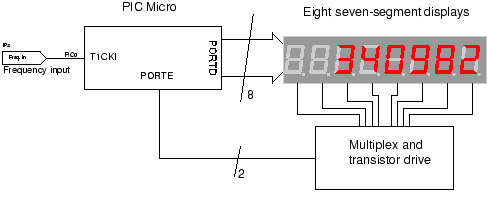
The circuit employs a straightforward approach for direct frequency measurement, which is user-friendly but results in the number of displayed digits varying with the input frequency. To consistently display all digits, a method known as reciprocal counting can be...
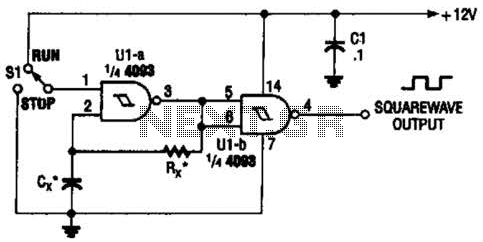
Two gates of the Quad 4093 are utilized to create an oscillator. The resistor (R) can range from approximately 5 kΩ to around 10 kΩ. The capacitor (Cx) can vary from about 10 pF to higher values, with the...

A project is proposed to construct a two-phone intercom system capable of functioning over a distance of up to 1 kilometer. The system will utilize the speaker of each phone to produce a ringing sound on the other end. The...
This circuit eliminates the traditional tungsten filament lamp amplitude regulator along with its associated time constant and linearity issues. Additionally, it addresses the reliability problems commonly found with lamps. The Wien Bridge oscillator is utilized, leveraging the fact that...
This circuit illustrates a remote control system utilizing a radio telephone circuit diagram. Features include the ability to switch appliances from any distance, overcoming various limitations. The remote control circuit employs radio frequency (RF) technology to facilitate wireless communication between...