
Pulse Width Modulator Using 555 IC

A pulse width modulator (PWM) is an essential component in various electronic applications, particularly in motor control, power regulation, and signal processing. The PWM signal is characterized by its ability to maintain a fixed frequency while adjusting the duration of the high state (duty cycle) based on an input modulating signal. This modulation allows for efficient control of power delivery to devices, enabling precise control over performance characteristics such as speed and torque in motors or brightness in LED lighting.
In a typical PWM circuit, the core components include a comparator, a reference voltage source, and a timing circuit. The comparator compares the modulating signal, which can be a sinusoidal waveform or any other varying signal, against a triangular or sawtooth waveform generated by the timing circuit. When the modulating signal exceeds the reference waveform, the output of the comparator switches high, creating a pulse. The width of this pulse is determined by the amplitude of the modulating signal at the moment of comparison, effectively varying the duty cycle.
The frequency of the PWM signal is determined by the timing circuit, which sets the rate at which the triangular or sawtooth waveform oscillates. The choice of frequency is critical and should be tailored to the specific application, balancing factors such as response time and efficiency. For instance, in motor control applications, a lower frequency might be preferable to reduce audible noise, while higher frequencies may be used in applications requiring rapid response times.
Additionally, filtering components may be included in the circuit to smooth out the PWM signal, converting it into a more stable DC voltage if needed. This is particularly useful in applications where a steady voltage is required, such as in power supplies or when driving analog devices.
Overall, the design of a PWM circuit involves careful consideration of component selection, waveform characteristics, and operational requirements to achieve the desired control and efficiency in electronic systems.Pulse width modulator produce a PWM signal, a pulse with a constant frequency but with the duty cycle vary according to a modulating signal. Here is the. 🔗 External reference
Related Circuits
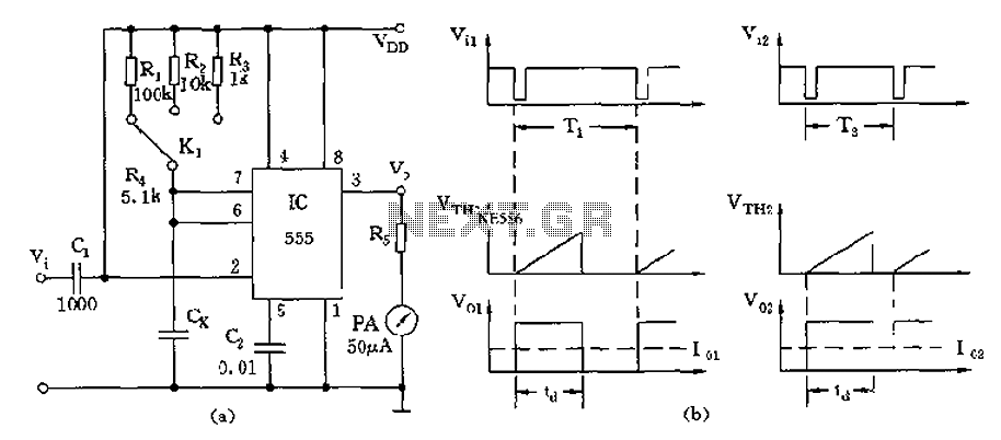
The circuit utilizes a 555 timer along with timing resistors R1 to R3 and a measured capacitance Cx to create a capacitance meter. The principle of capacitance measurement in a one-shot circuit is based on the relationship between the...
A drink mixer inspired by BAR2D2 utilizes a gravity-fed pump that operates on a 9V battery. The circuit incorporates a 555 timer to control the duration of the pump's operation. When connected directly to the battery, the pump functions...
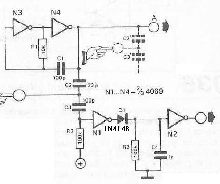
This touch sensor switch is designed using inverters (N1, N2) and several common electronic components. In the standby state, a signal is produced by the oscillator N3/N4 at the inputs of N1. When the touch sensor is activated, the...
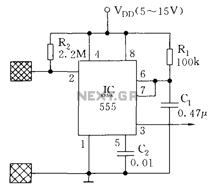
The proximity switch using the 555 timer functions as a monostable trigger circuit. The trigger pin (Pin 2) of the 555 timer is connected through a large resistor (R2) to the positive supply voltage (VDD) and is in a...
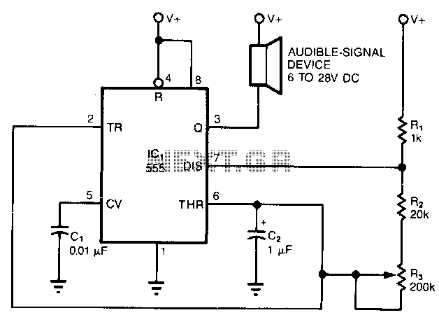
The simple circuit converts the continuous beep of an audible-signal device, such as a Mallory sonalert, into a unique warble or chirp. The values of resistor R and capacitor C2 determine the specific tone quality produced. With a 1kΩ...
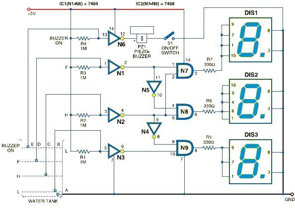
This schematic outlines a simple electronic circuit designed to indicate water levels using a 7-segment display. The circuit shows water levels by displaying 'L', 'H', and 'F' for low, half, and full levels, respectively. It is based on the...