
Simple Automatic Air Flow Detector Circuit and Circuit Board

The air flow detection circuit operates by utilizing the thermal properties of a filament incandescent lamp. When air flows over the lamp, it affects the temperature of the filament, which in turn alters its resistance. This change in resistance can be monitored to determine the presence or absence of air flow.
The LM339 operational amplifier is employed in this circuit to compare the voltage across the sensor with a predefined threshold. When air flow is detected, the voltage changes sufficiently to trigger the output of the LM339, which can then activate an LED indicator. The LED serves as a visual signal that air flow is occurring.
In terms of configuration, the circuit typically includes a power supply connected to the LM339, which is set up in a comparator mode. The filament lamp is connected in series with a resistor to form a voltage divider. The output from the LM339 can be connected to the anode of the LED, with the cathode connected to ground, allowing the LED to illuminate when air flow is detected.
This type of air flow detection circuit can be applied in various settings, such as HVAC systems, ventilation monitoring, or safety applications where air flow is critical. The simplicity of the circuit allows for easy integration into existing systems while providing reliable air flow detection.This circuit is a simple detection of air flow, this circuit can be signaled in the event of air flow. The sensor used is a filament incandescent lamps. Air Flow Detector, sensor, LED, LM339, op-amp,. 🔗 External reference
Related Circuits

These circuits are utilized for the detection of single-sideband (SSB) and continuous wave (CW) signals. The beat frequency oscillator (BFO) injection is generally in the range of 0.5 to 1 V rms for both circuits. The operational frequencies can...
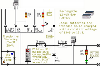
The following circuit illustrates an Alarm Power Supply Circuit Diagram. Features include a 1-amp current output, suitable for a Modular Burglar Alarm operating at 12 volts. The Alarm Power Supply Circuit is designed to provide a stable and reliable power...

A simple random number generator utilizing the 8051 microcontroller. The AT89S51 is the controller employed in this setup. The circuit design for the random number generator based on the AT89S51 microcontroller involves several essential components and connections. The AT89S51 microcontroller,...
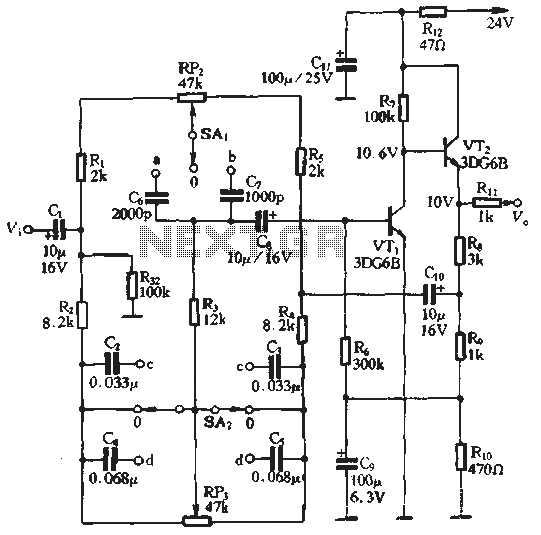
An attenuation switch is utilized to modify the pitch of a feedback control circuit's transition frequency, specifically for two treble controls. RP3 is designated for bass control, while SA1 and SA2 are employed to adjust the high bass control...
The LM1036 is a DC-controlled circuit designed for adjusting tone (bass/treble), volume, and balance in stereo applications such as car radios, televisions, and audio systems. It features an additional control input that enables straightforward loudness compensation. Four control inputs...
This simple alarm timer circuit is constructed using a 4060 integrated circuit, which features a stable oscillator with a relatively wide frequency range. The alarm timer circuit utilizes the CD4060 IC, which combines a low-frequency oscillator and a binary counter....