
Circuit Diagram Of Alarm Power Supply

The Alarm Power Supply Circuit is designed to provide a stable and reliable power source for a Modular Burglar Alarm system. The circuit typically consists of a transformer, rectifier, voltage regulator, and filtering components. The transformer steps down the mains voltage to a lower AC voltage, which is then rectified by a diode bridge to convert the AC voltage into pulsating DC.
The voltage regulator ensures that the output voltage remains constant at 12 volts, despite variations in input voltage or load conditions. Capacitors are employed for filtering to smooth out the pulsating DC, reducing ripple and providing a cleaner power supply to the alarm system.
The circuit is rated for a current output of 1 amp, making it suitable for powering various components of the burglar alarm, such as sensors, sirens, and control panels. Protection features such as fuses or circuit breakers may also be included to safeguard against overcurrent conditions.
Overall, this power supply circuit is essential for ensuring the proper functioning of a Modular Burglar Alarm, providing the necessary voltage and current while maintaining reliability and safety.The following circuit shows about Alarm Power Supply Circuit Diagram. Features: 1-amp current, suitable for the Modular Burglar Alarm, 12-volts .. 🔗 External reference
Related Circuits
The IEEE 802.3af standard defines the interaction between power-sourcing equipment and powered devices within a power-over-Ethernet system. The IEEE 802.3af standard, also known as Power over Ethernet (PoE), specifies the mechanisms by which electrical power is transmitted alongside data over...
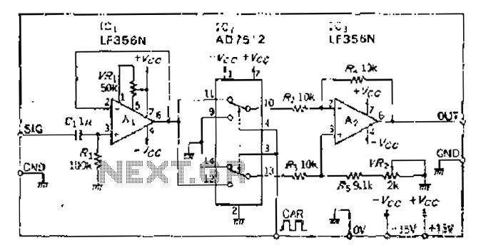
An analog switch (double loop, double-break) and a differential modulation amplifier are used in this circuit. The carrier control switch operates by switching contacts at specific times, inverting the input modulation wave. When the next carrier signal is applied...
The series of decibel meters functions to determine the signal strength level delivered to the speakers in an audio system. This decibel meter circuit is commonly referred to as VU meters in high-fidelity audio systems. The series of decibel...
This is a very simple FM receiver built using only one transistor. It does not utilize any chips or other active components. The output is connected to earphones; an amplifier circuit is required if the radio is to be...
A gas leak detector circuit that detects the leakage of LPG gas and alerts the user through audio-visual indications. The circuit operates off a 9V PP3 battery. A Zener diode is used to convert 9V into 5V DC to...
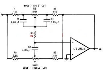
A simple tone control circuit can be designed using the LM833 operational amplifier along with a few external components. The LM833 is a dual general-purpose operational amplifier, specifically optimized for performance in audio applications. This tone control circuit utilizes...