
Stepper Motor Controller Schematic

The circuit described operates a unipolar stepper motor using a 6V power supply and a microcontroller interfaced through a CD4050 hex buffer. The CD4050 serves to buffer the microcontroller's output signals, ensuring adequate drive capability for the TIP122 transistor, which functions as a switch to control the motor coils.
The TIP122, a Darlington pair transistor, is used to handle the higher current required by the stepper motor. The connection of the emitter and collector to a 1N4007 diode is crucial for flyback protection, preventing voltage spikes generated when the motor coils are de-energized from damaging the transistor or the microcontroller.
The stepper motor in use is a unipolar type, which typically has six wires: four for the coils and two for the common connection to the power supply. The color coding indicates the function of each wire, facilitating correct connections. The motor's operation is controlled through a series of signals sent from the microcontroller, which are defined in the provided code snippets.
The code includes a `rotate` function that sequentially energizes the coils of the stepper motor to achieve rotation. The `delay` function introduces a timing mechanism to control the speed of rotation. The loop in the `main` function continuously calls the `rotate` function, allowing for ongoing operation of the stepper motor.
In summary, this circuit effectively demonstrates the control of a unipolar stepper motor using a microcontroller, a hex buffer, and a transistor, showcasing fundamental principles of motor control in electronic design.We are using 6v/2amps 1. 8degree stepper motor. In this circuit CD4050 hex buffer using to connect to the microcontroller. The output of cd4050 is connected to the TIP122 of the BASE. The Emitter and collecter is conneted to 1N4007 diode the colleter of tip122 is connected to the stepper motor coil. In this demo we are using Uni polar Stepper motor using 6wires, the color coding of the stepper motors
are Black coil 1, Red coil 2, Green coil 3, Yellow coil 4 and 2 white are connected to give 6V input supply voltage. #include "reg51. h" void delay(unsigned int y); void rotate() { P1=0x09; delay(30); P1=0x05; delay(30); P1=0x06; delay(30); P1=0x0a; delay(30); } void delay(unsigned int y) { int i, j; //delay subroutine for(i=0;i<=y;i+) for(j=0;j<=498;j+); } void main() { while(1) { rotate(); } }
🔗 External reference
Related Circuits
A common issue encountered is that individuals possess a schematic, also known as a circuit diagram, that they wish to construct. However, they discover that there are... Building a circuit from a schematic requires a clear understanding of the components...
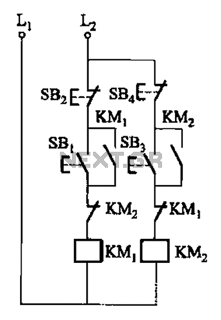
A, B, and two electric motors allow simultaneous operation through interlock control. The two motors can be connected in series with each other using normally closed contacts in the respective coil circuit. The circuit design facilitates the interlocking operation of...
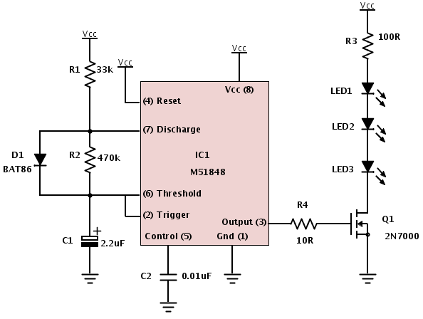
A Darlington connection-type transistor is utilized for driving the coil. In this configuration, two stages of transistors are connected in series, resulting in a high current gain, where the "hfe" of the Darlington transistor is the product of the...
The fan operates continuously in many PCs, which may not be necessary. A simple controller circuit can adjust the fan speed based on demand. This not only conserves energy but also minimizes noise irritation from the fan. Only three...
The circuit is compatible with all 2323 chips, but it is optimized for the AT90LS2323, which operates at a voltage range of 2.7 to 6 volts. The microcontroller utilized in this design is the AT90S2323, which functions effectively within...
This simple robot responds to light and avoids obstacles without the need for a microcontroller, programmer, or PC. The primary component in the circuit is a window discriminator, which functions as an advanced window comparator. Resistors R1 and R2,...