
Transistor based 3.3V-5V Level Translator
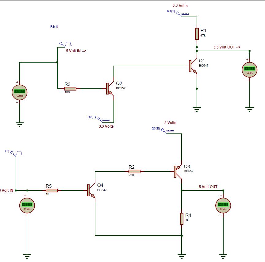
The circuit for voltage level translation between a 3.3V device and a 5V microcontroller typically employs a simple transistor switch configuration. The primary components include an NPN transistor, resistors, and the two devices that need to communicate.
In this setup, the 5V microcontroller sends a high signal (5V) to the base of the NPN transistor through a current-limiting resistor. This turns the transistor on, allowing current to flow from the collector to the emitter. The collector is connected to the 3.3V device's input pin, while the emitter is connected to ground. When the transistor is activated, it effectively pulls the 3.3V device's input to ground, representing a low signal.
Conversely, when the microcontroller sends a low signal (0V), the transistor is turned off, and the input pin of the 3.3V device is pulled high via a pull-up resistor connected to the 3.3V supply. This configuration ensures that the 3.3V device receives the correct voltage levels corresponding to the signals from the 5V microcontroller.
For a complete implementation, it is crucial to select appropriate resistor values to ensure proper current flow and to prevent damage to the components. The pull-up resistor value should be chosen based on the input characteristics of the 3.3V device to ensure reliable operation. The schematic can be simulated in Proteus, allowing for verification of the functionality before physical implementation.
This level-shifting method is commonly used in various applications where different voltage levels need to communicate effectively, ensuring compatibility and reliable data transfer between components operating at different voltages.Nowadays most of the devices are running on 3.3 volts, and likewise their communication levels also work on 3.3 volts. For example XBee runs on 3.3 volts and to interface it with microcontrollers running on 5V, one needs to translated voltages levels so that they both communicate.
This post gives a schematic of transistor based level translation with Proetus simulation 🔗 External reference
Related Circuits
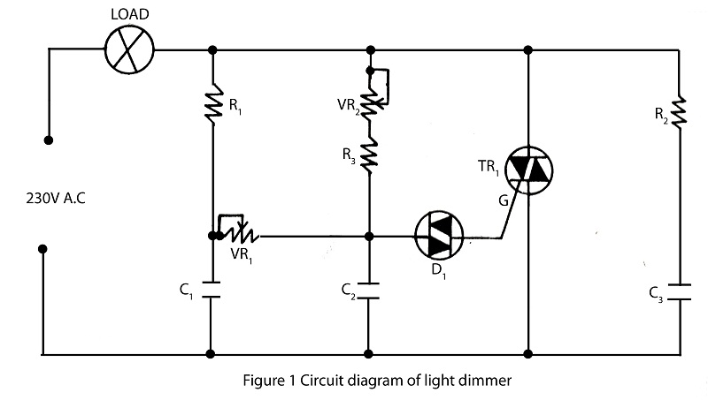
The lighting source, such as a bulb or tube light, illuminates based on its specified wattage. To achieve increased brightness, a higher wattage bulb must be used, while a lower wattage bulb is necessary for reduced brightness. However, it...
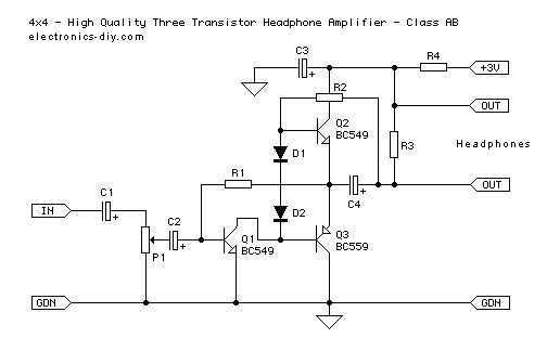
This is an improved version of a headphone amplifier I built many years ago. I wanted to share it because this simple circuit has done great service to me through all these years. It is very simple and reliable,...
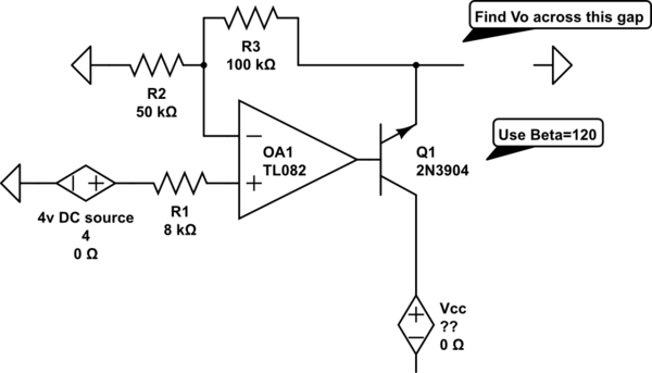
The voltage measured at 12V after the emitter is perplexing, especially when the output from the op-amp is +15V, suggesting a 3V drop across the transistor. This raises questions about the expected gain of 2, which would imply an...
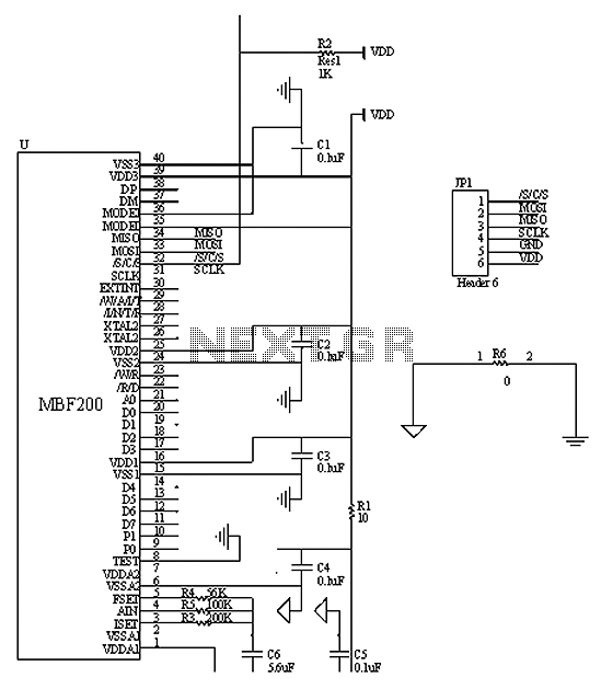
The ASIC design focuses on a highly integrated, low-power solution with a short development cycle to complete an FPGA design aimed at achieving a robust background system, which holds significant practical relevance and broad market potential. The project utilizes...
The three circuits described provide a constant current to the LED (or LEDs) when the supply voltage reaches 15V or higher. The second and third circuits can be activated or deactivated through the input line by turning on the...
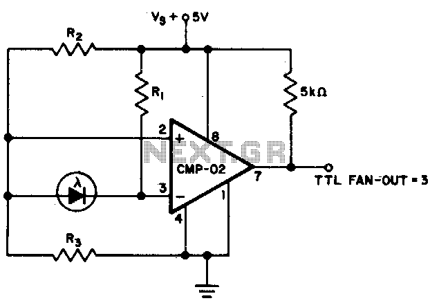
The output state changes at a photodiode current of 0 µA. For R1 = 2 MΩ, R2 = R3 = 5 MΩ. The described circuit likely involves a photodiode used in conjunction with resistors R1, R2, and R3 to create...