
Precision photodiode level detector

The described circuit likely involves a photodiode used in conjunction with resistors R1, R2, and R3 to create a voltage divider or a similar configuration that influences the output state based on the current generated by the photodiode. When light strikes the photodiode, it generates a current that varies with the intensity of the light. The critical point mentioned is when this current reaches 0 µA, indicating a threshold at which the output state transitions.
In this configuration, R1, with a resistance of 2 MΩ, may serve as a load resistor for the photodiode. The values of R2 and R3, both at 5 MΩ, suggest they could be configured as pull-up or pull-down resistors, or they might be part of a feedback loop in an operational amplifier setup.
The output state change at 0 µA indicates that the circuit is designed to detect the absence of light or a very low light condition. This output could be used in various applications such as light-sensing alarms, automatic lighting systems, or in optical communication systems where the presence or absence of light signals a state change.
The overall performance of this circuit will depend on the characteristics of the photodiode, including its responsivity and the wavelength of light it is designed to detect, as well as the power supply and any additional components that may be included in the circuit for signal conditioning or amplification. Proper selection and placement of components will ensure that the circuit operates effectively at the specified thresholds and provides reliable output states in response to varying light conditions.The output state changes at a photo diode current of 0 µA For Rl = 2 M, R2 = R3 = 5 M.
Related Circuits
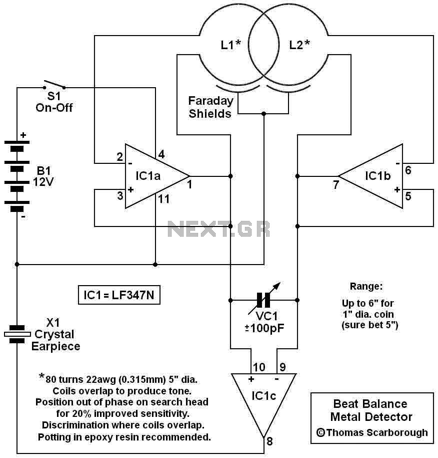
Here's a metal detector circuit that frequencies of the two oscillators are then mixed in similar fashion to BFO, to produce an audible heterodyne. On the surface of it, this design would seem to represent little more than a...
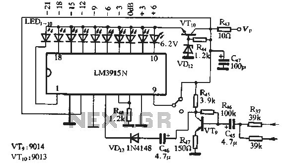
The circuit features a manual recording level control function. When in recording mode, the recording level is indicated by the LM3915N. The sound recording circuit, as illustrated in Figure 3-17, employs an RC network and an associated audio recording...
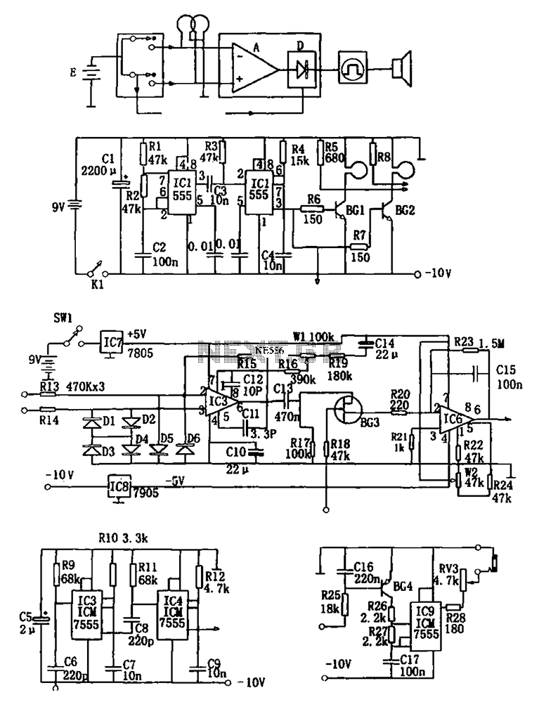
The figure illustrates a double coil metal detector circuit, which consists of a probe, a transmitter, a receiver, a timer, sound transmitters, and other components. The transmitter circuit, depicted in (b), is composed of a multivibrator (IC1, R1, R2,...
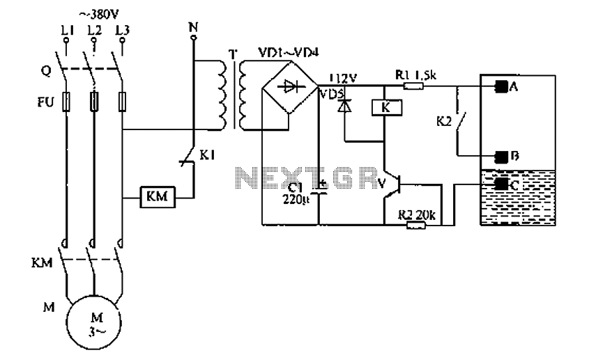
The liquid level automatic controller circuit consists of a power circuit, a level detection circuit, and a control implementation circuit. The power circuit is formed by a power transformer T, rectifier diodes YD1 to VD4, and a filter capacitor...
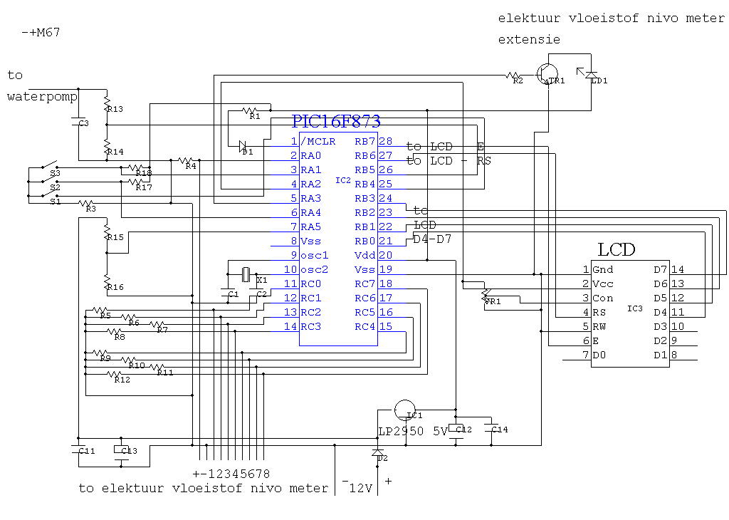
IC4 serves as a counter and oscillator combination, which is the pivotal component of the circuit. The oscillator generates an AC signal that is output on pin 7. This signal is routed through a voltage divider composed of resistors...
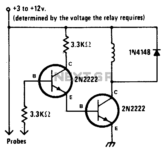
When the liquid level reaches both probes, the alarm is activated. When the water level recedes, the alarm is deactivated. The described circuit functions as a liquid level monitoring system utilizing two probes to detect the presence of liquid. The...