
VHF Audio Video Transmitter
The audio/video transmitter circuit operates within the VHF frequency range, specifically targeting channel 5, which is typically utilized for television broadcasting. The circuit's design incorporates a mixer and oscillator configuration to effectively modulate the audio and video signals. The primary component, transistor Q1, is pivotal in generating the carrier wave for the video signal. The resonant tank circuit, consisting of inductor L1 and trimmer capacitor VC1, ensures that the oscillation occurs at the desired frequency, allowing for efficient transmission of the video signal.
Transistor Q2 serves as a frequency modulator, where the audio input modifies the frequency of the 5.5 MHz signal produced by its oscillator circuit. This modulation process is crucial for embedding the audio signal within the RF carrier wave, enabling simultaneous transmission of audio and video. The coupling capacitors, C4 and C8, play a significant role in isolating the audio and video signals while allowing necessary signal transfer to the respective stages of the circuit.
In terms of construction, inductor L1 must be accurately wound on a 3mm core using 24 SWG enamelled wire, ensuring that the number of turns is precisely four. This specification is vital for achieving the correct inductance value necessary for the desired oscillation frequency. The circuit's power supply requirement of 12V DC is standard for such applications, and the simplicity of the calibration process allows users to adjust the trimmer capacitor VC1 for optimal reception on a standard television set.
Overall, this circuit is an effective solution for short-range audio/video transmission, suitable for various applications including home entertainment systems and personal video broadcasting. Its design emphasizes ease of assembly and tuning, making it accessible for hobbyists and professionals alike.The circuit presented here is a simple audio/video transmitter with a range of 3 to 5 metres. The A/V signal source for the circuit may be a VCR, a satellite receiver or a video game etc. A mixer which also operates as an oscillator at VHF (H) channel 5 TV frequency is amplitude modulated by video signal and mixed with frequency mo enna, contains video carrier frequency of 175. 25 Mhz and audio carrier frequency of 180. 75 Mhz. Then, the transmitter is a B-System of CCIR compatible. The circuit consists of transistor Q1 with its resonant tuned tank circuit formed by inductor L1 and trimmer capacitor VC1, oscillating at VHF (H) channel 5 frequency. Transistor Q2 with its tuned circuit formed using SIF coil and inbuilt capacitor forms oscillator. The audio signal applied at the input to Q2 results into frequency modulation of 5. 5 Mhz oscillator signal. The output of 5. 5 Mhz FM stage is coupled to the mixer stage through capacitor C8 while the video signal is coupled to the emitter of Q1 via capacitor C4 and variable resistor Inductor L1 can be wound on a 3mm core using 24SWG enamelled wire by just giving 4 turns.
Calibration/adjustment of the circuit is also not very difficult. After providing 12V DC power supply to the circuit and tuning your TV set for VHF (H) channel 5 reception, tune trimmer VC1. 🔗 External reference
Related Circuits
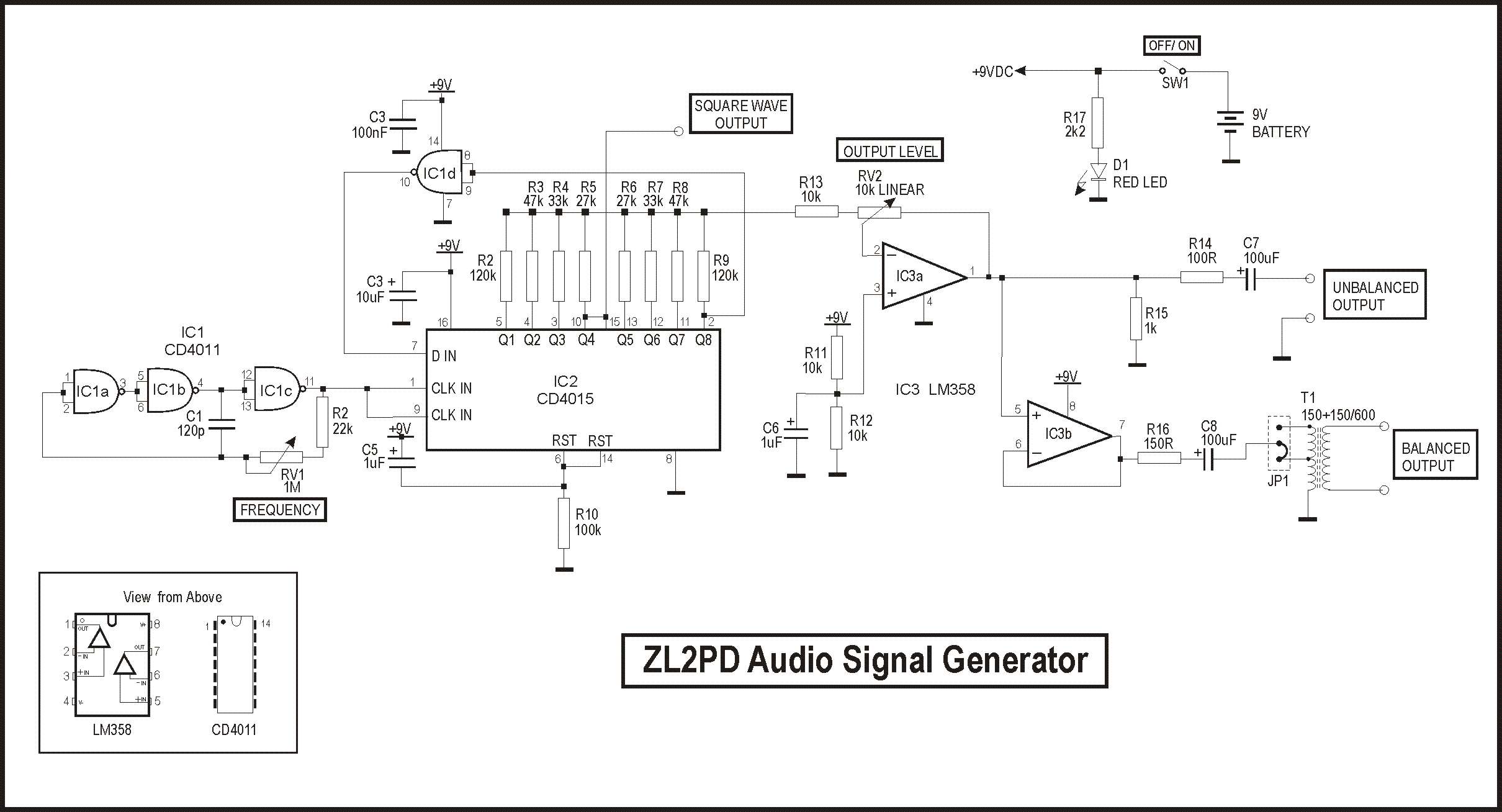
A couple of inexpensive CMOS integrated circuits are utilized to digitally generate audio sine waves across a broad frequency range in this compact battery-operated test instrument. The oscillator features both unbalanced and balanced outputs. Signal generators are frequently used...
Audio Amplifier with output power of either 100W or 130W. The output configuration can accommodate 2 transistors for 90W output or 4 transistors for 130W output. The PCB layout utilizes T3 on the heatsink. The component reference and values...
Nowadays, many audio-visual devices in homes are interconnected. This is particularly true for televisions, which may connect to DVD players, hard disk recorders, surround-sound receivers, and often PCs. This interconnection can lead to issues such as ground loops in...
This is a small but quite powerful FM transmitter having three RF stages incorporating an audio preamplifier for better modulation. It has an output power of 4 Watts and works off 12-18 VDC which makes it easily portable. It...
Bridged resistive sensing elements are commonly used in resistive type sensors and transducers. This type of sensor requires a biasing voltage to operate. The LM10 provides low... Bridged resistive sensing elements are integral components in various resistive sensors and transducers,...
This circuit illustrates a 6-12 channel TV transmitter coupling circuit diagram. It is designed to stabilize the 10 P operation within the 6-12 channel range. The 6-12 channel TV transmitter coupling circuit is essential for ensuring stable transmission across multiple...