
90-130W Audio Amplifier using 2N3773

The audio amplifier circuit is designed to deliver high power output, specifically targeting applications that require robust audio amplification. The amplifier can be configured to provide either 90W or 130W output, depending on the number of output transistors used. With two output transistors, the amplifier achieves a maximum output of 90W, while utilizing four output transistors allows it to reach the full 130W output capability.
The PCB layout is critical for ensuring proper thermal management and efficient signal flow. The designation T3 indicates a specific location on the heatsink where thermal dissipation components are mounted, which is essential for maintaining the reliability and performance of the amplifier under high load conditions.
The component specifications include resistors with different power ratings and values, which play a crucial role in setting the biasing and gain of the amplifier circuit. R1, with a value of 120K ohms and a power rating of 1/4W, is likely used in the input stage for signal conditioning. R2, at 3.3K ohms and rated for 1/2W, may serve as a feedback resistor, influencing the overall gain of the amplifier. R3, with a value of 5.6K ohms and a power rating of 1/4W, could be part of the biasing network, ensuring optimal operation of the output transistors. Finally, R4, also at 3.3K ohms and rated for 1/4W, may have a similar role to R2, providing stability and linearity in the amplifier's performance.
In summary, this audio amplifier circuit is designed for high output power with careful consideration of component selection and PCB layout to ensure effective thermal management and signal integrity, making it suitable for demanding audio applications.Audio Amplifier 100W or 130W Outputshould be2(out=90W) or 4(out=130W) audio power transistors. PCB and layout Use T3 on Heatsink Component Ref./Value Type R1 120K 1/4W Resistor R2 3K3 1/2W Resistor R3 5K6 1/4W Resistor R4 3K3 1/4W Resistor.. 🔗 External reference
Related Circuits
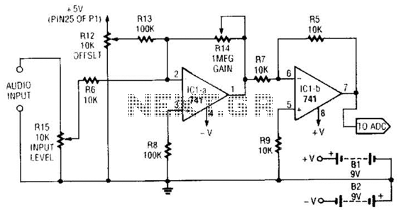
This simple general-purpose driver for an analog/digital converter uses two 741 IC devices with adjustable gain and offset. Other op-amps might be substituted, but some circuit adjustments might be needed. The circuit consists of two operational amplifiers (op-amps) from the...
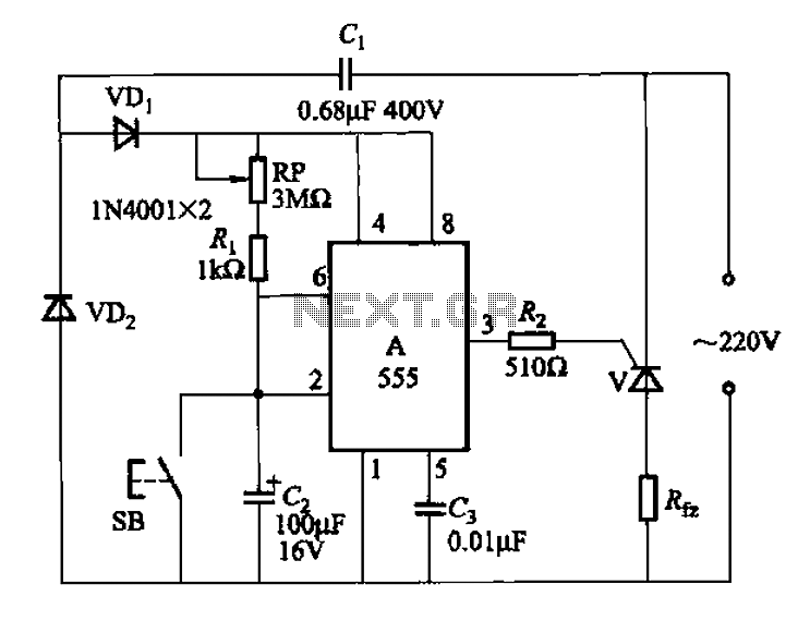
The 555 integrated circuit (IC) is utilized in a delay circuit configuration. It transitions from a high to a low output state when a button (SB) is pressed. The output remains high for a specified delay period before transitioning...
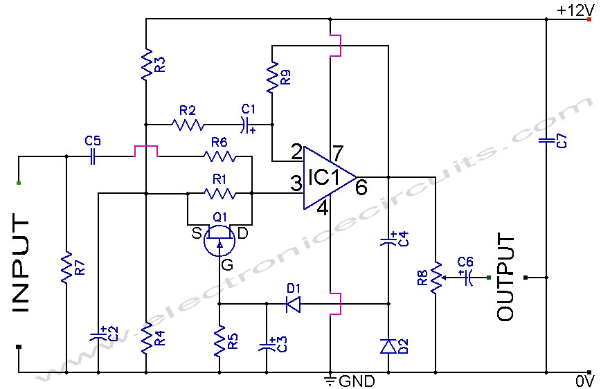
A section of the operational amplifier's output signal is rectified using 1N4148 diodes, followed by filtering, and is then directed to the gate of the FET input shunting circuit. As the output voltage increases, additional input shunting occurs, which...
This circuit was designed and manufactured in the 1980s. Since then, it has operated without issues. There are no significant constructional challenges, aside from the usual considerations: ensuring the appropriate power supply voltage, selecting a suitable heatsink, and properly...
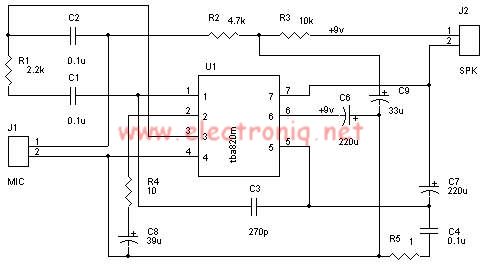
A very simple audio amplifier circuit can be designed using the TBA820M audio amplifier integrated circuit with just a few electronic components. This audio amplifier project features a high gain that allows for the detection of sounds underwater. The...
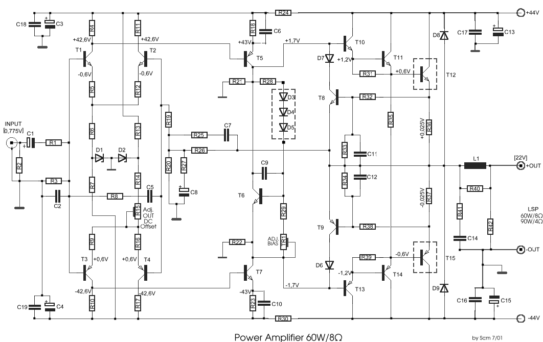
In the drawing, a simple but powerful power amplifier is presented. Its difference from classic designs, which use differential amplifiers in their input, is that this amplifier uses a complete NE5534 at its input. Thus, it is necessary to...