YUV/YCbCr to RGB converter
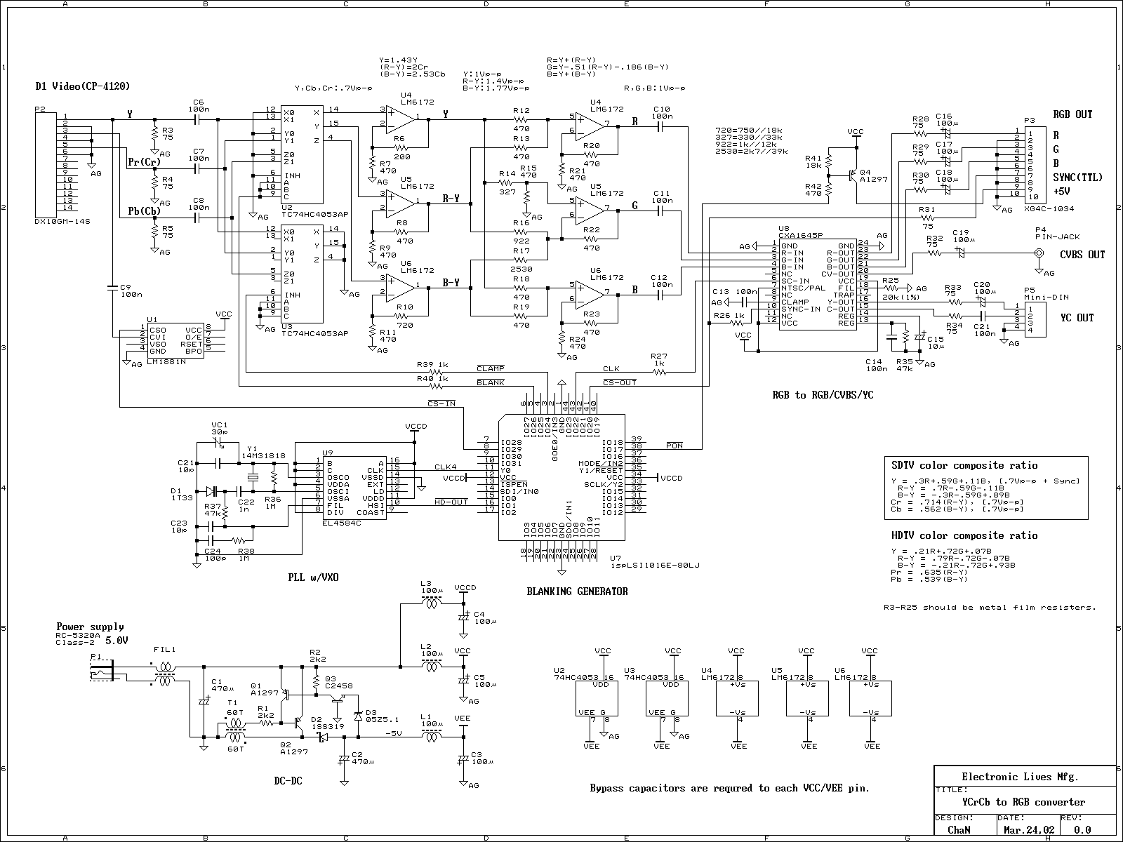
The device functions as a video recorder, DVD player, and TV game console, featuring a component video output. The component video signal resembles an RGB video signal; however, it is incompatible with RGB monitors.
The device's component video output is designed to provide high-quality video signals by separating the video information into multiple components. This method enhances the image quality compared to composite video signals, as it reduces interference and allows for higher resolution displays. The component video output typically consists of three separate signals: Y (luminance), Pb (blue minus luminance), and Pr (red minus luminance). This separation enables better color accuracy and detail in the video output.
It is important to note that while the component video signal shares similarities with RGB signals, they are fundamentally different in terms of signal structure and compatibility. RGB signals transmit color information through three separate channels (red, green, and blue), whereas component video uses a different encoding method. As a result, component video outputs cannot be directly connected to RGB monitors, which are designed to interpret RGB signals.
For optimal performance, the device should be connected to a compatible display that supports component video inputs. This setup will ensure that the full potential of the video quality is realized, providing an enhanced viewing experience for video playback and gaming. Users should refer to the specifications of their display devices to confirm compatibility with component video signals.Video recorder, DVD player and TV game, have component video output. The component video signal is like RGB video signal, but it cannot connect to RGB monitor. 🔗 External reference
