
audio-video modulator circuit
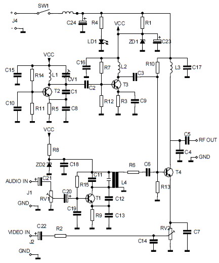
The circuit designed for converting audio and video signals into a UHF TV signal serves a crucial function in enabling the connection of various video sources, such as cameras, to standard television sets. The use of the LH0032 operational amplifier in the video amplifier circuit ensures high-speed processing of the signals, which is essential for maintaining signal integrity and quality during transmission.
The components listed in the parts list are selected to optimize performance and reliability. Resistors R1 through R15 provide necessary impedance matching and signal conditioning, while capacitors C1 to C4 are employed for coupling and filtering purposes. The choice of a 10µF capacitor for C1 aids in blocking DC components while allowing AC signals to pass through, ensuring that only the desired audio and video signals are amplified.
In the laser communication system, the modulation of the laser beam's intensity in accordance with the audio signal enables wireless transmission of sound. This method is advantageous for applications requiring secure and interference-free communication. The conversion of laser intensity variations into voltage changes is critical for accurate signal reception.
The Active Tone Control circuit, or ACTOR, utilizes the Baxandall tone control system to enhance audio playback quality. By actively boosting bass and treble frequencies, this circuit allows users to customize their audio experience, making it suitable for various listening environments and preferences.
The UHF band TV antenna booster circuit is designed to improve the reception of UHF signals, particularly in areas with weak signal strength. The band-pass filter formed by the specified components ensures that only the desired frequency range is amplified, while unwanted signals are attenuated. This results in clearer and more reliable television reception.
Lastly, the turbo bass circuit effectively enhances low-frequency audio signals, making it an excellent addition to audio systems that require improved bass response. The use of operational amplifiers in this design allows for precise control over the amplification process, ensuring that the output maintains fidelity to the original audio source. Overall, these circuits represent a diverse range of applications in audio and video signal processing, showcasing the versatility and effectiveness of modern electronic design.The circuit will convert an audio and video signal into a UHF TV signal. It`s desired to connect a video signal originating from a camera or other video source to a normal TV set. The audio and video signal is converted into a UHF TV signal so. This is schematic diagram of a video amplifier ci rcuit, built based very high speed opamp IC LH0032. Parts List: R1 = 15K ©+15K © R2-3-4 = 10K © R5, R6, R7, R8, R9 = 1K © R10 = 820 © R11 = 1M © R12 = 100 © trimmer R13, R14, R15 = 47 © R14 = 10K © C1 = 10uF 63V MKT C2, C3, C4 = 100nF/63V C3 = 4. 7pF. This is the circuit diagram of laser communication system that transmit the sound or music signals by way of a laser beam.
The intensity of the laser beam varies together with the amplitude of the sound signal. The variation within the intensity of the laser beam is converted into a variation in the voltage level. The following diagram is the schematic diagram of Active Tone Control circuit, or we often call thic circuit as "ACTOR" Active Tone Control or ACTOR is a electronic audio circuit that serves to increase the Loudness (Bass and Treble audio signal) is active because it uses the Baxandall system.
This circuit does not use a. This is the circuit diagram of UHF band TV antenna booster with 15dB gain power. This low cost antenna booster is simple and easy to build. This circuit formed based on BF180 UHF Transistor. The first stage is an band pass filter constructed by the C1, CV1, L1, L4, C7 and C3, the second stage. This circuit is a circuit of the turbo bass that can be used to multiply the low frequency sound signals (bass) on your audio system.
This circuit is an active circuit in which the incoming audio signal from the input will be strengthened in the first op-amp. The second op-amp that will filter out the. 🔗 External reference
Related Circuits
This schematic diagram illustrates a single-chip Theremin circuit. A Theremin is an electronic musical instrument that detects hand movements to control tones and frequency. The circuit employs two separate Colpitts LC oscillators to generate a beat frequency. The frequencies...
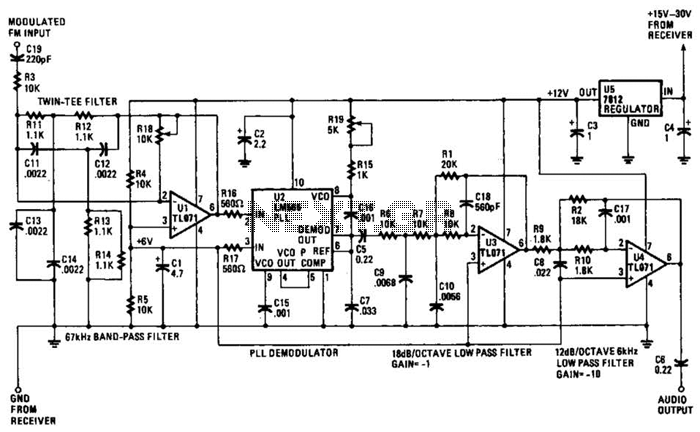
The operational amplifier (Op Amp) U1 and its associated components form a 67-kHz bandpass filter. A twin-T network, consisting of four 1100-ohm resistors and four 0.0022-microfarad capacitors, is integrated into the feedback loop of the op amp. This configuration...
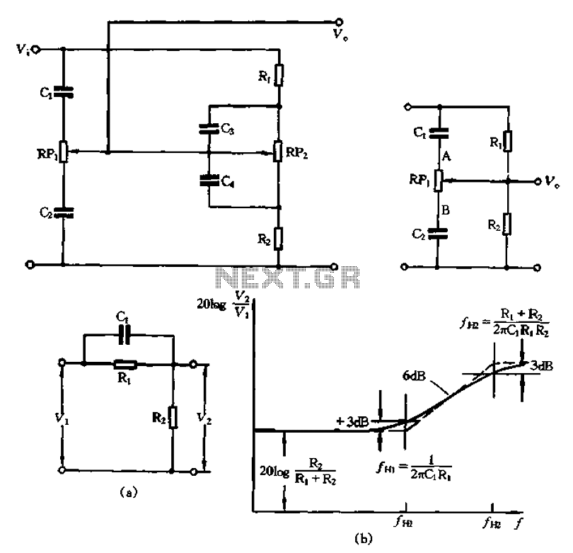
The circuit illustrated in Figure 1-560 represents a treble control potentiometer. Due to the larger capacitance values of C3 and C4 compared to C1 and C2, high-frequency signals can treat C4 as a short circuit. Consequently, the treble adjustment...

This is an application circuit for calibration known as a high voltage AC calibrator circuit. A key aspect of sine wave oscillator design is the stable control of amplitude. In this circuit, the amplitude is stabilized through servo control,...
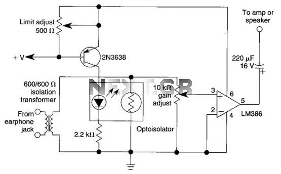
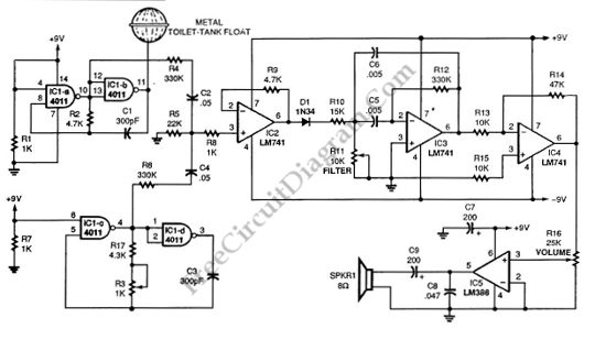
An optoisolator is utilized as an attenuator in this circuit. When the LM386 draws more current from audio signals, the 2N3638 activates, which biases the optoisolator on, thereby reducing the volume. The circuit employs an optoisolator to achieve signal attenuation,...
This circuit explains alternate wireless switching using an ultrasonic sensor. The distance of the switching range should be more than 10 meters. The described circuit employs an ultrasonic sensor to facilitate wireless switching, allowing for the activation or deactivation of...