
connect a lcd to a picaxe

The circuit involves interfacing a 16x2 Liquid Crystal Display (LCD) with a PICAXE-18M2 microcontroller. The 16x2 LCD is a popular display module that can show two lines of 16 characters each. The PICAXE-18M2 is a versatile microcontroller that allows for easy programming and control of various electronic components.
To connect the LCD to the PICAXE-18M2, the following connections should be made:
1. **Power Connections**:
- Connect the VSS pin of the LCD to the ground (GND) of the PICAXE.
- Connect the VDD pin of the LCD to the +5V power supply.
2. **Control Pins**:
- The RS (Register Select) pin should be connected to one of the digital output pins of the PICAXE (e.g., pin C.0).
- The RW (Read/Write) pin should be connected to ground to set the LCD in write mode.
- The E (Enable) pin should be connected to another digital output pin (e.g., pin C.1).
3. **Data Pins**:
- The data pins D0 to D7 of the LCD can be connected to the digital output pins of the PICAXE (e.g., D.0 to D.7). However, for simplicity, it is common to use only the upper four data pins (D4 to D7) for 4-bit mode operation.
- Connect D4 to pin C.2, D5 to pin C.3, D6 to pin C.4, and D7 to pin C.5 of the PICAXE.
4. **Additional Components**:
- A potentiometer (typically 10kΩ) can be connected between the VDD and GND, with the wiper connected to the V0 pin of the LCD. This is used for adjusting the contrast of the display.
The programming code for the PICAXE-18M2 should include initialization commands for the LCD, setting it to 4-bit mode, and providing functions to write characters and strings to the display. The typical sequence of commands includes initializing the display, setting the cursor position, and sending data to be displayed.
This setup allows for the effective use of the LCD with the PICAXE-18M2, enabling the display of text-based information in various applications. Proper power management and signal integrity should be maintained to ensure reliable operation of the LCD module.The circuit diagram and code on how to connect an 16x2 LCD to a PICAXE-18M2 microcontroller.. 🔗 External reference
Related Circuits
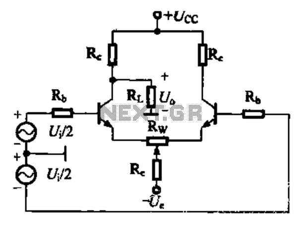
A comparison of four connection methods and features of a differential amplifier circuit is presented. The circuit demonstrates a magnification of a single tube with half the earnings, effectively countering common-mode negative feedback effects. The Common-Mode Rejection Ratio (CMRR)...
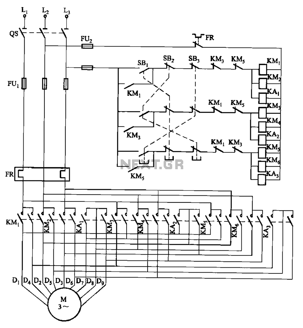
The circuit depicted in Figure 3-115 utilizes contactors and double buttons, allowing for speed conversion without the need to press the stop button. The buttons SBi, SBz, and SB3 correspond to high, medium, and low-speed operation, respectively. This circuit design...
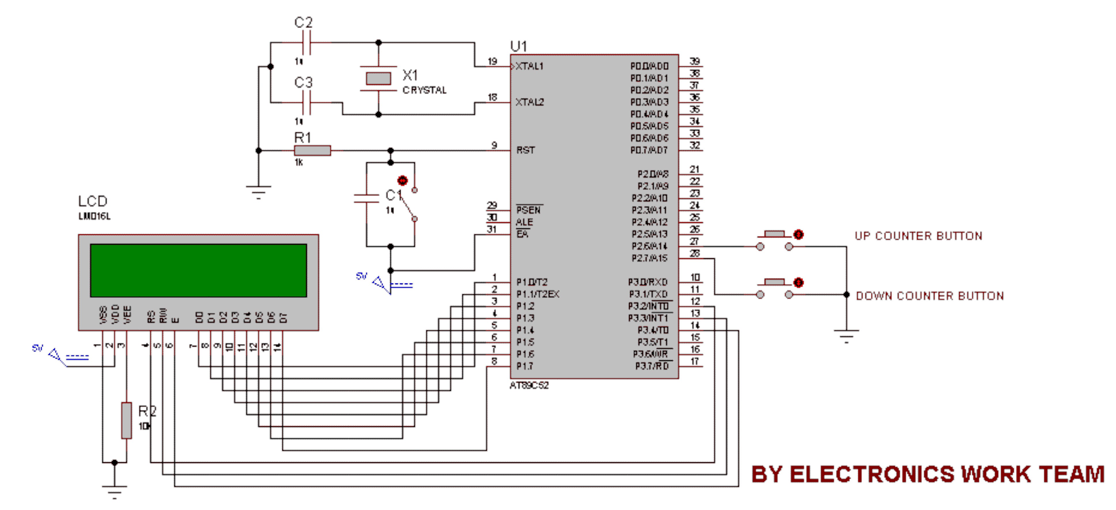
This circuit utilizes a 16x2 LCD to display a count value using an 8051 microcontroller. The maximum count value is set to 99. The circuit consists of the 8051 microcontroller, a 16x2 LCD, and two switches designated for incrementing...
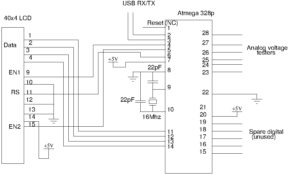
Drive a four-line LCD panel using an Arduino. The project initially aimed to control the LCD for displaying arbitrary information but evolved to include functionalities such as timekeeping, EEPROM read/write operations from the Atmel 328p, and voltage measurement. Multiple...
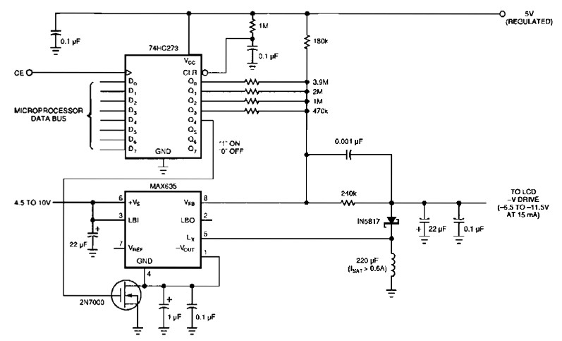
The following figure's switching regulator generates a negative voltage from the notebook battery supply. The microprocessor data bus drives a 4-bit DAC (74HC273), which can vary the regulator output between 6.5 to 11.5 V. This arrangement enables a staircase...
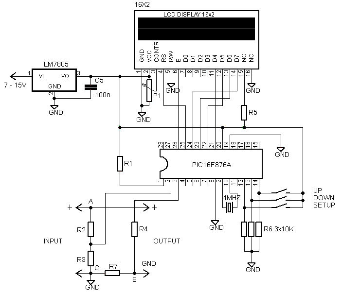
Voltmeters and ammeters with a PIC microcontroller can be utilized to measure voltage and current simultaneously. The configuration of voltmeters and ammeters using the PIC16F876A serves as a data processor for voltage and current measurements. This circuit employs a...