
2Y-2Y-2Y-connected three-speed motor contactor control circuit

This circuit design incorporates a series of contactors that facilitate the control of motor speed in an efficient manner. The use of double buttons enables seamless transitions between different speed settings without interrupting the motor's operation.
The SBi button initiates high-speed operation, engaging a specific contactor that connects the motor to the full supply voltage, thereby maximizing its performance. The SBz button is intended for medium-speed operation, which typically involves a resistor in series with the motor to limit current and reduce speed effectively. Lastly, the SB3 button activates low-speed operation, likely utilizing a different configuration of resistors or contactors to achieve the desired lower speed setting.
The circuit is designed to enhance user experience by eliminating the need to stop the motor before changing speeds, which can improve productivity and reduce wear on mechanical components. The careful arrangement of the contactors ensures that the motor receives the appropriate voltage and current for each speed setting, while also providing necessary protection against overload conditions.
Overall, this circuit exemplifies a practical and efficient approach to motor speed control, utilizing simple yet effective components to achieve desired operational flexibility. Circuit shown in Figure 3-115. It uses contactors and double buttons, so when converting speed without press stop press ugly, can be directly converted. SBi, SBz button and SB3 are high, medium and low speed operation button.
Related Circuits
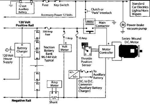
After charging the batteries for many hours with the 12V charger and PowerCheqs, a drive of about 5 miles resulted in the low battery light activating. The PakTrakr indicated that the battery adjacent to the most positive battery required...
This circuit is a stable frequency counter with an accuracy of 5 significant digits. It operates within a frequency range of 0 to 30 MHz and has an input sensitivity greater than 100 mV. The probe connects to the...
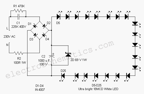
This white LED light illuminates the porch with cool white light. The circuit features a simple and energy-saving design. Its current consumption is practical. The white LED light circuit is designed to provide efficient illumination while minimizing energy usage. The...
In its simplest form, a voice-over unit is just a microphone and change-over switch feeding an amplifier, the output from the microphone having priority over the amplifiers audio signal when the "push-to-talk" switch is pressed. In this circuit, a...
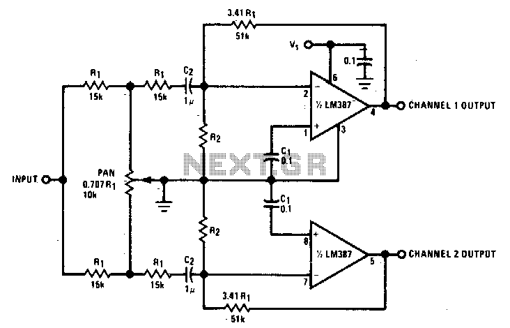
This panning circuit, also known as a panoramic control circuit, allows for the adjustment of the perceived position of a microphone's input across two output channels. This effect is frequently utilized in mixing consoles within recording studios. Panning enables...
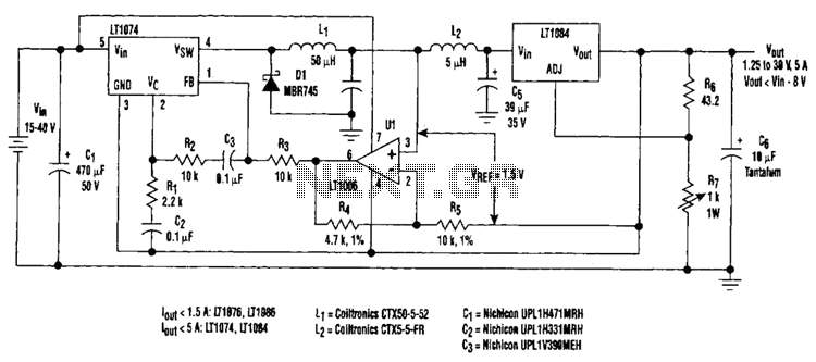
Large input-to-output voltage differentials, caused by wide input voltage variations, reduce a linear regulator's efficiency and increase its power dissipation. A switching preregulator can reduce this power dissipation by minimizing the voltage drop across an adjustable linear regulator to...