
curve tracer adaptor schematics

The circuit design integrates several critical components to ensure precise measurements and reliable operation. The dual trace oscilloscope allows for simultaneous observation of voltage and current, facilitating the analysis of circuit behavior under various conditions. The use of operational amplifiers IC2a and IC2b is pivotal in providing the necessary signal conditioning and isolation, which minimizes the impact of cable capacitance on the measurements. The relay system enhances the versatility of the testing setup by enabling quick switching between different probes, thereby allowing for comparative analysis without the need for extensive manual reconnections.
Moreover, the adjustable sine wave input is crucial for testing a wide range of devices, from low-voltage sensitive components to those requiring higher voltage levels for functional verification. The specification of using shielded coaxial cables and low-resistance probe leads emphasizes the importance of maintaining signal integrity and reducing noise interference, which are critical factors in accurate electronic measurements.
In summary, this oscilloscope-based testing unit serves as a comprehensive tool for evaluating the performance of various electronic components, providing essential insights into their operational characteristics while ensuring measurement accuracy through careful design considerations.This unit employs a dual trace oscilloscope with X-Y function as a display to test and demonstrate the action of circuits and components such as transistors, diodes, zener diodes, and terminated and unterminated transformers. A low frequency sinewave (ie 10Hz - 1kHz) is applied to op amp IC2a via potentiometer VR1 to set the "X" and "Y" levels for
the X-Y display on the scope. The output of IC2a is applied to the X input via R4 and IC2b and also to Probe 1 via the contacts of relay 1. IC2b provides a low impedance drive for the X input and also isolates the X input cable capacitance from probe 1.
The current flowing into the probes develops a voltage across R4 which is processed by IC2d and applied to the CRO Y input to represent current. The scope display thus represents an X-Y graph where voltage across a circuit under test is displayed on the X axis (horizontal) and the current though it displayed on the Y axis (vertical).
With a calibrated scope this equates to 1mA/V. IC1 and a relay are included to enable two probes to be used and comparisons made between a known good device and a faulty one. The relay should be a low capacitance reed type. By using the scope`s X and Y gain controls, the sinewave applied to the device under test should be adjustable from a few millivolts up to 24V peak-peak to get a very useable display.
Thus, the unit can be used on voltage sensitive devices and at the other end of the scale apply enough voltage to check the operation of, say, a 10V zener diode. Note that all devices should be tested in the unpowered condition. If used for in-circuit tests, the effects of circuit components will need to be taken into account. Shielded coax leads should be used for the X and Y inputs and the probe leads should have zero resistance.
Normal scope probes should not be used as these usually have significant built-in resistance which will interfere with measurements. 🔗 External reference
Related Circuits
The circuit's operating principle is that if you make a pulse width proportional to inductance, and keep the pulse frequency and amplitude constant, and then pass the pulse through a low pass filter so that only the average voltage...
Create a repository of circuits and service data for vintage valve and transistor radios. While many resources are available online, they often come at a cost. The intention is to share circuits and manuals with others rather than profit...
This chapter contains circuit diagrams for several power supplies designed for pulsed solid-state lasers. These include units suitable for driving the widely used Hughes ruby and YAG rangefinder laser assemblies, one utilizing the flash from a disposable pocket camera,...
This circuit is a resonant twin-T filter. Its purpose is to provide a reasonable imitation of a low-pass response, which it achieves effectively. The schematic illustrates two variations: one with self-oscillation and one without. The version built includes oscillation....
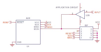
It is crucial to design the PCB layout correctly to enable seamless In-System Programming (ISP) of AVR microcontrollers. This guide addresses common issues encountered and provides typical AVR ISP circuit schematics. It focuses on Serial Programming, known as ISP,...
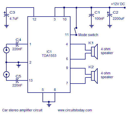
A car stereo amplifier circuit that can be used in automobiles, designed using the Class-B audio amplifier TDA1553, complete with a circuit diagram and schematics. The car stereo amplifier circuit utilizes the TDA1553, a Class-B audio amplifier known for its...