
Car Stereo Amplifier Diagram and Schematics using TDA1553 IC

The car stereo amplifier circuit utilizes the TDA1553, a Class-B audio amplifier known for its efficiency and performance in automotive applications. This integrated circuit is designed to deliver high-quality audio output while minimizing power consumption, making it suitable for use in vehicles where space and energy efficiency are critical.
The TDA1553 can typically provide an output power of up to 2 x 22W at a load of 4 ohms, which is ideal for driving car speakers. The circuit configuration generally includes input capacitors to block any DC offset from the audio source, ensuring that only the AC audio signal is amplified. Feedback resistors are employed to set the gain of the amplifier, allowing for customization based on the specific requirements of the application.
Power supply decoupling capacitors are essential for stabilizing the voltage supplied to the amplifier, minimizing noise and distortion in the audio output. Additionally, the circuit may incorporate thermal protection features to prevent overheating, ensuring reliable operation over extended periods.
The schematic representation of the amplifier circuit typically includes connections for input, output, and power supply, clearly indicating the placement of each component. The layout should be designed to minimize interference and optimize signal integrity, with careful attention paid to the routing of power and ground traces.
Overall, the TDA1553-based car stereo amplifier circuit is a robust solution for automotive audio systems, providing excellent sound quality and efficiency while being easy to implement with standard electronic components.A car stereo amplifier circuit that can be used in automobiles, designed using Class-B audio amplifier TDA1553, with circuit diagram and schematics.. 🔗 External reference
Related Circuits
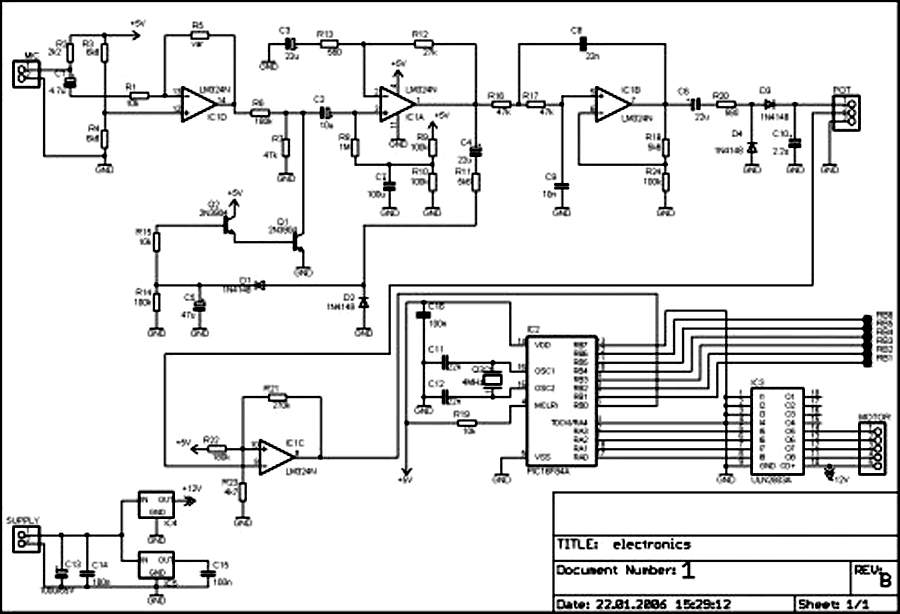
External circuit converts bass beat of music into pulses. The motor is controlled by them. If there's bass beat recognized then the motor rotates one direction (in full stepping) for a predefined time then stops. If the second beat...
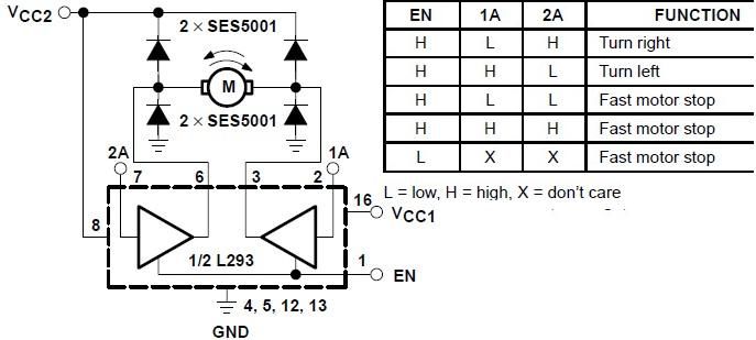
The L293 is designed to provide bidirectional drive currents of up to 1 A at voltages ranging from 4.5 V to 36 V. The L293D variant is capable of delivering bidirectional drive currents of up to 600 mA at...
The figures below illustrate using opamps as active 2nd order filters. Three 2nd order filters are shown, low pass, high pass, and bandpass. Each of these filters will attenuate frequencies outside their passband at a rate of 12dB per...
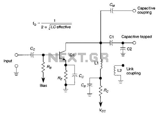
This basic tuned LC amplifier can be used with three output coupling methods: capacitive coupling output, capacitive tapped output, or link-coupled output. The tuned LC amplifier is a fundamental circuit used in various applications, including radio frequency (RF) amplification and...
It may be necessary to use 10 diodes and various resistors, particularly when utilizing white LEDs. Refer to the Troubleshooting section in step 3 for more details. A sheet of 0.005-inch thick matte drafting film was purchased from a...
The following circuit illustrates an Electric Car Audio Project. Features include a Rockford Fosgate Punch 4080DSM amplifier, which operates in a bridged 2-channel configuration at 4 ohms for component speakers. The Electric Car Audio Project utilizes the Rockford Fosgate Punch...