
eprom schematics

The EPROM Emulator serves as a versatile tool for testing and developing electronic circuits that utilize EPROM (Erasable Programmable Read-Only Memory) chips. This device allows engineers and hobbyists to simulate the behavior of EPROMs without the need for physical chip programming, significantly streamlining the development process.
The emulator typically interfaces with a microcontroller or a computer, allowing users to upload binary files that represent the data they wish to emulate. It may feature a user-friendly interface for easy file management and configuration. The circuit design generally includes a microcontroller, memory management components, and communication interfaces such as USB or serial connections to facilitate data transfer.
Key components of the circuit may include:
1. Microcontroller: Acts as the core of the emulator, processing commands and managing data flow.
2. Flash Memory: Provides the storage space for emulated EPROM data, allowing for quick data retrieval and modification.
3. Voltage Regulators: Ensure that all components receive the appropriate voltage levels for optimal performance.
4. Communication Interfaces: Such as USB or serial ports, which enable connection to external devices for data uploading and downloading.
5. User Interface: May consist of buttons, LEDs, or a display to provide feedback and control options to the user.
The design should also include protective features such as over-voltage and over-current protection to safeguard the internal components. Additionally, proper layout considerations should be taken into account to minimize noise and interference, which could affect the accuracy of the emulation.
Overall, the EPROM Emulator is an essential tool for anyone working with EPROM technology, providing a flexible and efficient means of testing and development.Electronic Project Eprom Emulator This EPROM Emulator was designed to compliment the EPROM Programmer (Mark 2).. 🔗 External reference
Related Circuits

This page introduces an engaging project designed by Toon Beerten, titled "DIY LED Mood Lamp." This project serves as an intriguing addition to any room, guaranteed to impress viewers. The lamp features a color-fading effect that enhances its visual...

Korg has released schematics for the analog drum synthesis section of its Monotribe synthesizer and step-sequencing rhythm machine. The schematics focus on the components responsible for generating drum sounds, which are the most interesting and modifiable aspects of the...

This document presents plans for a simple ground plane antenna that is effective in the FM band (88-108 MHz). It is constructed from a small plastic disk. The 6 x 6 loop antenna, designed by Graham Maynard, is highlighted...
An FM tracer was developed using the LM3909 integrated circuit (IC) along with several supporting components. This 1.5V FM tracker serves as an indicator of revenue sources by emitting a signal through an LED. The FM tracking circuit operates...

This chapter presents a variety of circuits for basic power supplies, including both line-powered and inverter types, some of which feature regulators, modulation inputs, and additional functionalities. Several circuits have been reverse-engineered from actual commercial products, and others, designed...
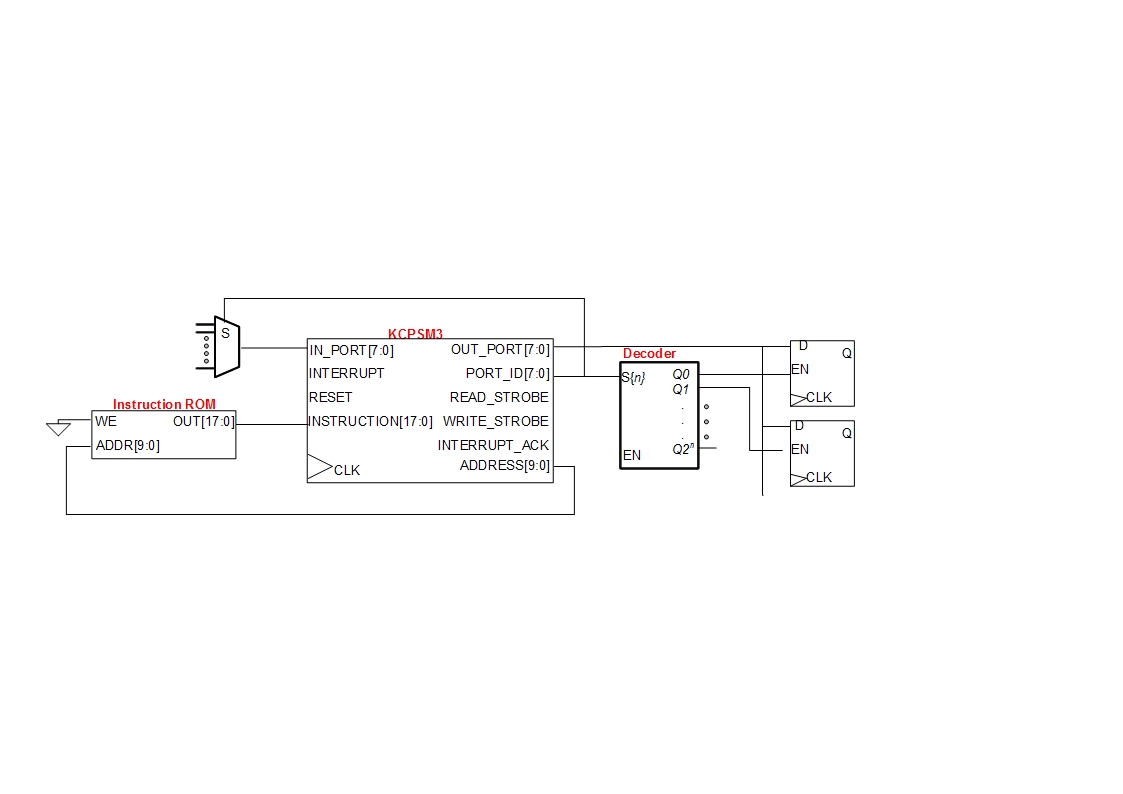
A small digital design utilizes a Xilinx Picoblaze softcore processor. Creating acceptable quality schematics has proven to be frustrating and time-consuming. Previous attempts to integrate existing schematics from LTSpice or Eagle into the documentation yielded unsatisfactory results, appearing fuzzy...