
Tracking FM Transmitter Schematics Schematic Diagram
The FM tracer circuit based on the LM3909 IC is designed to provide a simple yet effective solution for tracking signals in the FM band. The core of the circuit is the LM3909, which is a low-power IC designed for LED flashing applications, but its capabilities can be adapted for FM transmission. The circuit operates at a nominal voltage of 1.5V, making it suitable for use with small battery cells, which are commonly available and easy to use.
The circuit's design includes a few essential components: a power source (battery), the LM3909 IC, an LED for visual indication, a variable capacitor (C3) for tuning the frequency, and a standard 12-inch antenna for signal transmission. The consumption current of 3.7 mA ensures that the circuit can operate efficiently without draining the battery quickly.
To set the operating frequency, the user can connect the FM receiver to the output of the FM tracer. By adjusting the variable capacitor C3, the user can fine-tune the frequency until the receiver picks up the signal emitted by the FM tracker. The LED provides a visual confirmation that the circuit is functioning correctly, lighting up when the correct frequency is achieved.
The use of a standard antenna enhances the range and effectiveness of the FM tracker, allowing it to transmit signals over a reasonable distance. This project not only serves as an educational tool for those interested in electronics but also provides practical experience in circuit assembly, frequency tuning, and signal transmission. Overall, the 1.5V FM tracker represents a valuable learning opportunity in the field of electronics, combining theory with hands-on application.FM tracer was prepared using the LM3909 IC and some supporting components. 1. 5V FM trackers This will provide an indicator of revenue sources by providing a signal emitted by the LED. FM tracking uses a source voltage of the battery cell and fruit consumption current is 3. 7 mA. After completion of assembling Tracker FM 1. 5V, then the next step is setting the operating frequency of the FM tracker is, for convenience we can use the FM receiver and adjust the working frequency FM 1. 5V Tracking (tracking transmitter) by regulating C3. Have been obtained if the working frequencyTrackingFM 1. 5V (tracking transmitter) then the corresponding LED will light emitted by the transmitter information such as sound through an FM receiver is terdengan.
1. 5V FM tracker (tracking transmitter) can use a regular 12-inch antenna. Playing and learning electronics that will be happy, 🔗 External reference
Related Circuits
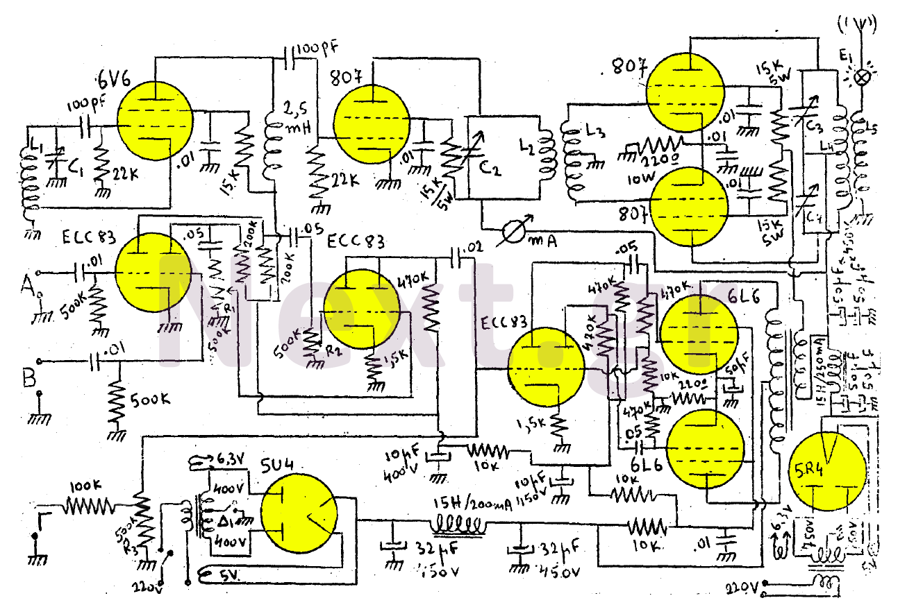
This transmitter consists of a 6V6 oscillator that excites an 807 buffer. The final stage includes two 807 tubes arranged in a Push-Pull configuration. The amplifier is built with three series-connected double-triodes (ECC83) and concludes with two 6L6 tubes...
Mobile phone battery chargers available in local markets can be quite expensive. The circuit presented here offers a low-cost alternative for charging cellular phone batteries or battery packs with a rating of 7.2 volts. This low-cost phone battery charger circuit...
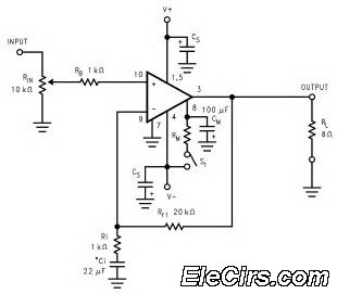
The LM3886 high-performance audio power amplifier circuit schematic is a crucial component in sound reproduction within audio systems. This audio power amplifier utilizes the LM3886 integrated circuit to enhance sound quality and output. The LM3886 is a high-performance audio power...
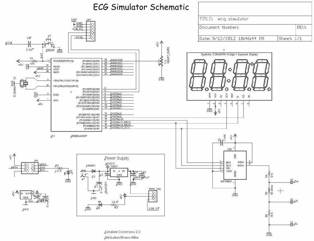
Below is the final schematic for the Menta ECG Simulator project. LadyAda's Eagle schematic for the Menta was used as a starting point. The Menta ECG Simulator project is designed to emulate the electrical signals produced by the heart, providing...
The controller for a Hybrid Power Plant (HPP) block diagram consists of 440 Wp photovoltaic modules, a 1 kW wind turbine, and a 5 kW diesel engine as a backup. The HPP functions as a centralized PV and wind...

This is a CMOS-compatible (and ideally also TTL-compatible) input that includes over-voltage and under-voltage protection. Schmitt triggers are utilized to accommodate inputs with long transition times. It has been verified to function at frequencies up to 30 MHz. The described...