
ir receiver circuit

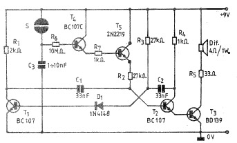
The IR receiver circuit typically comprises several key components, including a photodiode or phototransistor, a resistor, an LED, and a power supply. The photodiode or phototransistor serves as the primary sensor, converting the incoming infrared light pulses from the transmitter into an electrical signal. When the IR LED emits a 38 kHz modulated signal, the photodiode detects this signal and generates a corresponding output.
The circuit's simplicity is one of its main advantages, making it suitable for educational purposes or basic remote control applications. The resistor is often used to limit the current flowing through the photodiode or phototransistor, ensuring its safe operation. The LED serves as an indicator, visually demonstrating the detection of the IR signal.
In terms of configuration, the photodiode or phototransistor is connected to the power supply, and its output is linked to the LED. When the IR signal is received, the circuit allows current to flow through the LED, causing it to blink as an indicator of successful signal reception. The design can be further enhanced by incorporating additional components such as amplifiers or filters, depending on the specific application requirements.
Overall, this IR receiver circuit is an effective and efficient solution for applications requiring basic infrared signal detection, providing a clear visual indication of signal reception through the blinking LED.This is a very simple and easy to make IR receiver circuit. This infrared receiver circuit is using only few components and it is able to receive 38KHz carrier signal. The working of this circuit is simple when ever the IR LED receive any signal from 38KHz transmitter it will blink LED in the circuit.
🔗 External reference
Related Circuits
A simple thermostat circuit that can control a relay to supply power to a small space heater through the relay contacts. The relay contacts must be rated above the current requirements for the heater. Temperature changes are detected by...
A simple and practical electronic bell circuit can be constructed using the provided schematic diagram. This circuit can function as a doorbell or an alarm system. It utilizes only a few transistors along with several common components. The circuit...
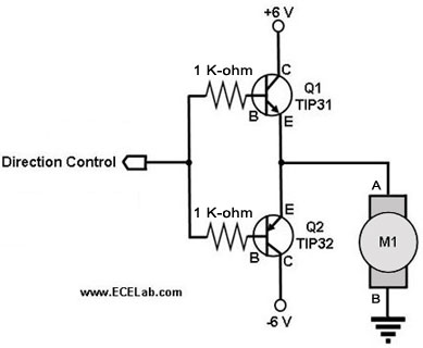
The following circuit illustrates a two-transistor DC motor driver circuit diagram. This circuit utilizes the TIP32 transistor. Features: operates in... The two-transistor DC motor driver circuit is designed to control the operation of a DC motor using two NPN transistors,...
An RF power amplifier is a type of electronic amplifier used to convert a low-power radio-frequency signal into a larger signal of significant power, typically for driving the antenna of a transmitter. It is optimized for high efficiency, high...
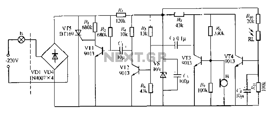
This circuit describes a sound and light control delay system for a walkway stairs light switch. It involves various components including 220V AC electric bulbs, diodes (VD1-VD4), and resistors. The circuit utilizes a rectifier regulator to stabilize the voltage...
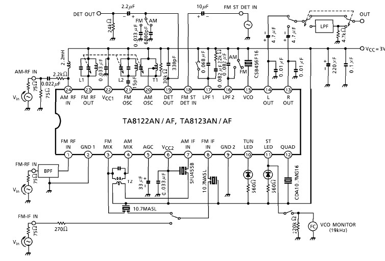
A simple low-power AM/FM radio receiver electronic project can be designed using the TA8122 integrated AM/FM receiver, manufactured by Toshiba Semiconductor. This radio receiver circuit can be utilized for portable radio applications or similar devices. The TA8122 radio receiver...