
Two-Transistor DC Motor DriverCircuit Using The TIP32 Transistor

The two-transistor DC motor driver circuit is designed to control the operation of a DC motor using two NPN transistors, which function as switches. The TIP32, a PNP transistor, is often employed in this configuration due to its capability to handle higher currents and voltages, making it suitable for driving motors.
In this circuit, the two NPN transistors are connected in a complementary push-pull configuration. When a control signal is applied to the base of the first NPN transistor, it turns on, allowing current to flow from the power supply through the motor and into the collector of the first transistor. This action causes the motor to rotate in one direction. Simultaneously, the second NPN transistor remains off, preventing current from flowing through it.
When the control signal is switched to the second transistor, it turns on, redirecting the current flow through the motor in the opposite direction, effectively reversing its rotation. This capability provides bidirectional control of the motor, which is essential for applications requiring precise movement, such as robotics or automated systems.
The circuit typically includes additional components, such as diodes for flyback protection, which safeguard the transistors from voltage spikes generated when the motor is switched off. Capacitors may also be included to filter out noise and stabilize the power supply.
Overall, this two-transistor DC motor driver circuit is a robust solution for controlling DC motors, offering simplicity in design while providing effective control over the motor's direction and speed.The following circuit shows about Two-Transistor DC Motor Driver Circuit Diagram . This circuit using the TIP32 Transistor. Features: runs in .. 🔗 External reference
Related Circuits
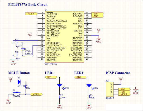
This project involves a basic LED blinking circuit utilizing the PIC16F877A microcontroller. It features two LEDs connected to the PIC16F877A, with the source code adapted from the 16F template. The circuit design consists of the PIC16F877A microcontroller, which serves as...
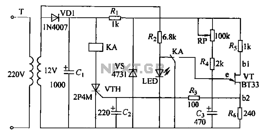
The circuit consists of a delay loop, discriminators, output circuits, power supply, and indicator lights, divided into five parts. The power regulation is achieved through a resistor (R), while the power regulator is constructed using a voltage source. In...
In this project, an embedded system is designed for tracking and positioning vehicles using the Global Positioning System (GPS) and Global System for Mobile Communications (GSM). The AT89S52 microcontroller interfaces with various hardware peripherals. The system continuously monitors a...
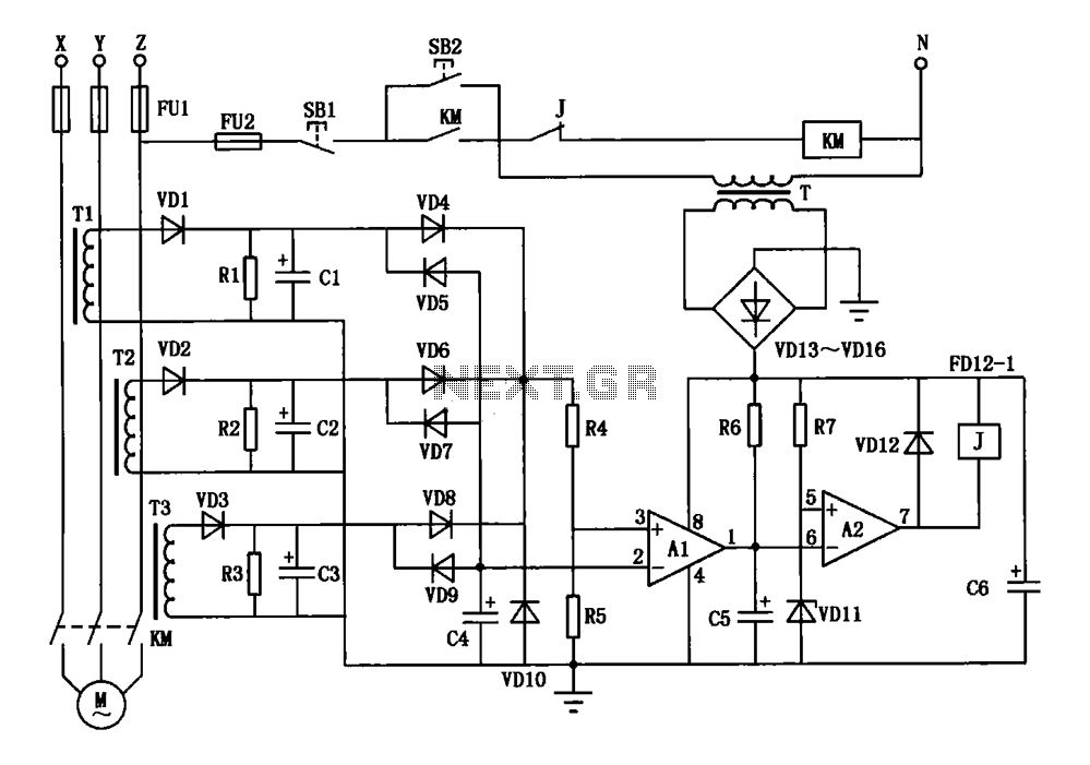
A current three-phase motor phase protection circuit is designed to detect three-phase current using homemade small current transformers T1, T2, and T3. The current signals are collected by rectifiers VD1, VD2, and VD3, while capacitors C1, C2, and C3...
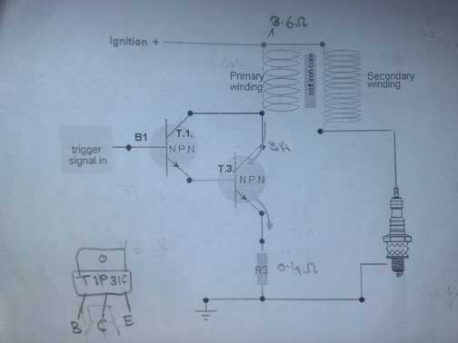
A request for assistance has been made regarding the development of a transistor ignition system to replace the point breaker in a motorcycle. The individual has researched extensively online but has not found a simple and effective circuit. The...
Audio Amplifier with output power of either 100W or 130W. The output configuration can accommodate 2 transistors for 90W output or 4 transistors for 130W output. The PCB layout utilizes T3 on the heatsink. The component reference and values...