
led blinking 8051 microcontroller keil c tutorial at89c51

The 8051 microcontroller family, including the AT89C51, is widely used in embedded systems due to its versatility and ease of use. The AT89C51 is particularly popular because of its reprogrammable nature, allowing developers to update firmware as needed. The microcontroller operates at a clock speed determined by the external crystal oscillator, which is a crucial component for timing operations. The two 22pF capacitors connected to the crystal help to filter noise and stabilize the oscillator's frequency, ensuring reliable operation.
The EA pin, which stands for External Access, must be tied to VCC to enable the internal program memory. This configuration allows the microcontroller to execute code stored in its internal memory, which is essential for running applications. The absence of an internal power-on reset necessitates an external reset circuit, typically involving a resistor and capacitor connected to the RST pin. This external reset ensures that the microcontroller starts in a known state after power is applied.
The programming of the AT89C51 requires a dedicated programmer, which in this case is equipped with a CP2102 USB to UART bridge. This interface facilitates communication between the microcontroller and a PC, allowing for the transfer of the compiled hex file. The choice of programming software is vital; tools like Flash Magic can be utilized for programming microcontrollers without an in-system programming (ISP) option.
In addition to the hardware setup, it is essential to ensure that the correct drivers for the CP2102 are installed on the computer. Once the drivers are in place, the programming utility can be used to upload the hex file to the microcontroller, enabling the execution of the desired application. Proper attention to the power supply connections, oscillator setup, and reset circuitry will ensure the reliable operation of the AT89C51 in various applications, from simple control tasks to more complex embedded systems.Basically 8051 controller is Mask‚ programmable‚ means it will‚ programmed‚ at the time of manufacturing and will not‚ programmed‚ again, there is a derivative of 8051 microcontroller, 89c51‚ micro controller‚ which is‚ re-programmable. This device also have Timer, Serial Port interface and Interrupt controlling you can use these according to your need.
VCC and GND of AT89C51 is not shown in the above circuit diagram. VCC should be connected to +5 and GND should be connected to Ground of the power supply. AT89C51 needs an oscillator for its clock generation, so we should connect external oscillator. Two 22pF capacitors are used to stabilize the operation of the‚ Crystal Oscillator. ‚EA should be strapped to VCC for internal programG‚executions. AT89C51 has no internal Power On Reset, so we have to do it externally through the RST pin using Capacitor and Resistor. When the power is switched ON, voltage across capacitor will be zero, thus voltageG‚acrossG‚resistor will be 5V and reset occurs.
As theG‚capacitorG‚charges voltage across theG‚resistorG‚gradually reduces to zero. The circuitG‚may beG‚simulated using Proteus. If you haven`t yet started with Proteus, please go through this tutorial. You can buy Proteus fromG‚ Labcenter Electronics. hi there. I have a atmel programming kit for AT89C51. This has the interface CP2102 USB to UART master controller to communicate with the computer. I have no problem with IDE. Now I want to fuse the hex file in to my controller. I searched in the net and found driver for my programmer interface (USB to UART). So the interface communicaiton has no problem. Now I need a utility to fuse the program in to MC. Could you please suggest me a good utility with download url to fuse programs in my AT89C51 It will be so helpful to me. Thanks for the reply. yes you are correct. But actually I don`t need drivers, coz I already found it. This I have stated very clearly in my previous post. All I need is a tool/utility to fuse my hex file in to my AT89C51. Let me make it clear. For example, I have been using phillips P89V51RD2 before this. It has an ISP. So my burn setup will have an MC with serial (MAX232) system connected board. And I use PL2302 usb to serial converter so that I can connect my MC board serial port to system usb port.
so I have to use PL2302 driver installed on my sys and thru Flash magic I could burn my hex thing to MC IC. In this case, it has no ISP thing like phillipse. So I need a programmer kit. This programmer kit has in build CP2102 USB to UART bridge controller and thus it demands a driver.
That, I already installed it. But I have to have a fuse program to push the hex file from system to controller IC. Thats all. Correct me if I am wrong. After buying the Atmel programmer kit, in home only I came to realise that the program CD is damaged. So, I need help. 🔗 External reference
Related Circuits
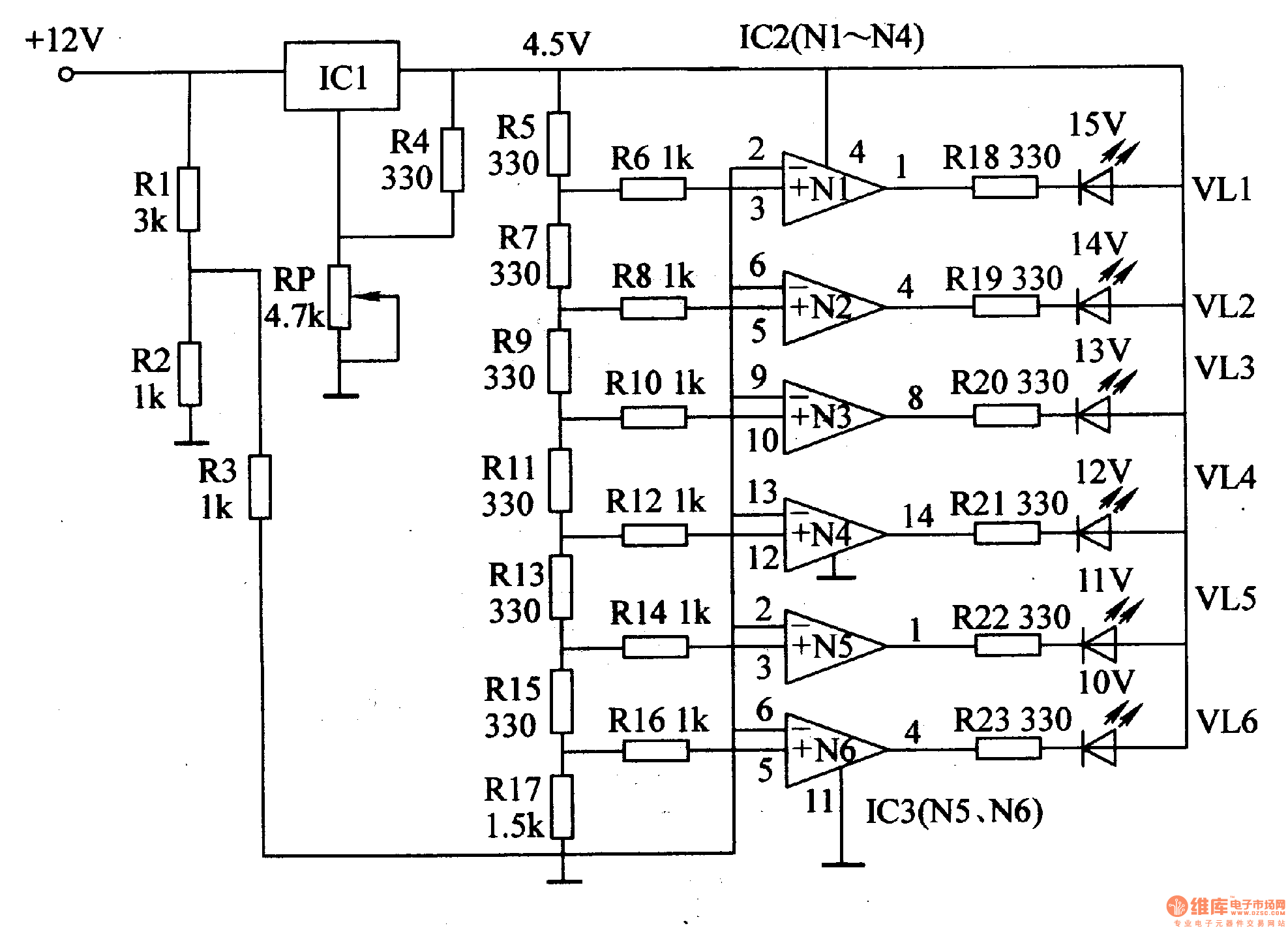
This document introduces an LED car voltmeter constructed using the op-amp LM312 and LED components. It is designed to display six voltage levels ranging from 10V to 15V, with each level representing a 1V increment. The working principle of...
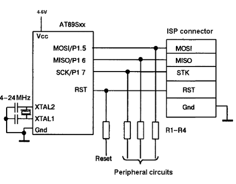
The AT89C family of microcontrollers features a parallel programming interface for flash memory. To write information, a programming voltage of 12V is required, and nearly all pins of the ports are utilized for this purpose. Consequently, parallel programming is...
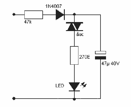
I needed a pulsating light for a certain signaling. Voltage was 230V. So I decided to make a simple circuit, consisted of a LED diode, two capacitors, two resistors, a diac and a diode. Activity of the circuit is...
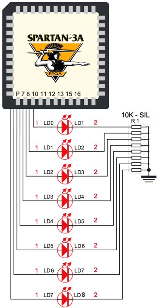
The Spartan-3an board features eight LEDs connected to FPGA I/O pins. The cathode of each LED is connected to ground through a 330-ohm resistor. To illuminate a specific LED, the corresponding FPGA control signal must be set to High. The...
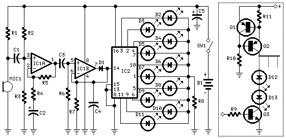
The basic circuit illuminates up to ten LEDs in sequence, synchronized with the rhythm of music or speech detected by a small microphone. The expanded version can drive up to ten strips, each containing up to five LEDs, powered...
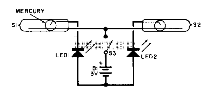
This electronic level utilizes two LED indicators in place of an air bubble. When the surface tilts to the right, one LED illuminates; conversely, if it tilts to the left, the other LED illuminates. Both LEDs light up when...