
The LED car voltmeter (2)
")
The LED car voltmeter circuit is an essential tool for monitoring vehicle battery voltage. The op-amp LM312 serves as the core component, providing the necessary amplification and precision for voltage measurement. The circuit operates within a voltage range of 10V to 15V, effectively indicating the battery status through a series of LEDs.
The regulator circuit ensures that the voltage supplied to the op-amp and other components remains stable, regardless of fluctuations in input voltage. This is achieved through a three-terminal voltage regulator IC, which maintains a constant output voltage. The potentiometer (RP) allows for fine-tuning of the output voltage, enabling calibration of the voltmeter for accurate readings. Resistor R4 is used to limit the current flowing through the circuit, protecting sensitive components from damage.
The Vref circuit generates a stable reference voltage that is crucial for the accurate operation of the op-amp. This reference voltage is compared with the sampled input voltage from the vehicle's battery. The voltage sampling circuit captures the battery voltage and feeds it into the op-amp for processing.
The LED display drive circuit is responsible for illuminating the appropriate LED corresponding to the measured voltage level. As the battery voltage varies, the op-amp outputs a signal that activates the corresponding LED in the display, providing a clear visual indication of the battery's voltage status.
In summary, this LED car voltmeter circuit efficiently monitors vehicle battery voltage using an LM312 op-amp and a well-structured design comprising a regulator circuit, Vref circuit, voltage sampling circuit, and LED display drive circuit. This configuration ensures reliable performance and accurate voltage readings, making it a valuable tool for automotive applications.Here is to introduce the LED car voltmeter which is made of the op-amp LM312 and LED, it can display 6 gears of voltages, 10-15V, each gear is 1V. The working principle of the circuit The LED car voltmeter consists of the regulator circuit, Vref circuit, sampling voltage circuit and LED display drive circuit, see as figure 7-76.
The regulator circui t consists of the 3-terminal regulator circuit IC, potentiometer RP and resistor R4. 🔗 External reference
Related Circuits
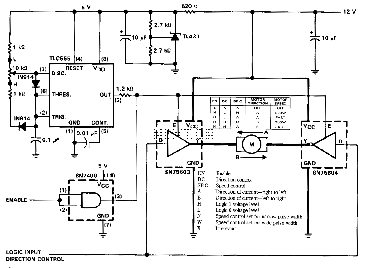
The figure illustrates a reversible DC motor drive application with adjustable speed control. The D inputs for these drivers are complementary and can be tied together and driven from the same logic control for bidirectional motor drive. The enables...
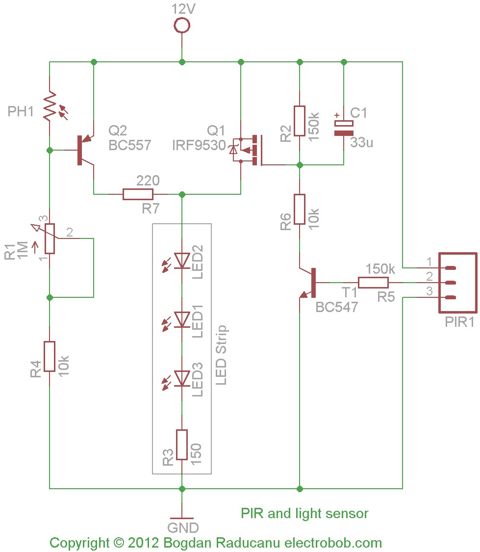
Recently, LED strips were purchased from a local electronics shop to replace spotlights in the kitchen. The chosen strips emit a cold white light, which is effective for nighttime illumination, resembling a moonlight hue. Operating at 12V, they consume...
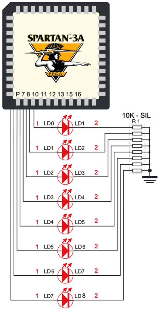
The Spartan-3an board features eight LEDs connected to FPGA I/O pins. The cathode of each LED is connected to ground through a 330-ohm resistor. To illuminate a specific LED, the corresponding FPGA control signal must be set to High. The...
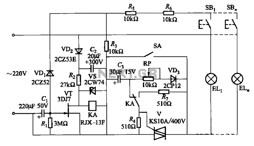
The circuit illustrated in Figure 2-50 utilizes a field effect tube and a combination of electronic components to create a unique self-lighting controller. The working lamp remains illuminated at a reduced brightness rather than being completely turned off, which...
This audio mixer circuit schematic is designed around four current-controlled amplifiers, all integrated within the SSM2024 IC. The audio mixer circuit utilizes the SSM2024 integrated circuit, which features low-noise, high-performance operational amplifiers suitable for audio applications. The SSM2024 is particularly...
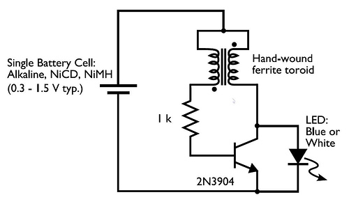
In the circuit diagram for the Joule Thief, the common point of the toroid is the connection at the top of the hand-wound ferrite toroid, located in the upper right of the diagram. This connection leads to the positive...