
plc circuit diagram
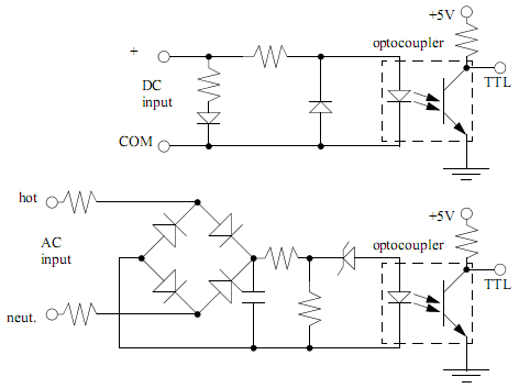
The operation of PLC input and output cards is critical for ensuring reliable communication between the PLC and external devices. Input cards are designed to interface with sensors and input devices, receiving signals that may vary in voltage levels. The need for an external power supply arises because the input card itself does not generate the necessary voltage to power these devices. The ladder logic diagram serves as a visual representation of the connections and logic flow, facilitating easier understanding and troubleshooting during installation and maintenance.
In the input circuitry, the use of optocouplers plays a pivotal role. These components allow for the safe transfer of signals between different voltage domains while preventing high voltages from affecting the PLC's internal components. The design typically includes resistors to limit current and ensure that the optocoupler operates within its specified range. Additionally, protection diodes may be included to prevent damage from reverse polarity, ensuring that the circuit remains functional even in adverse conditions.
Output modules operate similarly, acting as interfaces between the PLC and external loads, such as motors or lights. These modules require an external power source to energize the connected devices. The conversion from the 5VDC logic level to higher voltage levels is achieved through the use of optocouplers or relays, which can handle the higher currents and voltages needed for the external circuits. The isolation provided by these components protects the PLC from potential damage caused by surges or faults in the external circuitry.
Overall, the integration of input and output cards within a PLC system is essential for creating a robust and flexible control environment. Proper circuit design, including the use of optocouplers and protective components, ensures that the system can operate safely and effectively across a variety of applications.PLC input cards rarely supply power, it means that needs external power supply for the inputs and sensors. Below is an Input card and Ladder Logic diagram that shows how to connect an AC input card. The PLC inputs must convert a variety of logic levels tothe 5VDC logic level used on the data bus. This can be done with circuits similar as the picture below. Basically the circuits condition the input to drive an optocoupler. This electrically isolates the external electrical circuitry from the internal circuitry. Other circuit components are used to guard against excess or reversed voltage polarity. As with the input modules, output modules rarely supply any power, but instead act as switch. External power supplies are connected to the output card and it will switch the power on or off for each output. PLC outputs must convert the 5VDC logic level on the PLC data bus to external voltage levels. The circuits will show on the picture below. Basically the circuits use an optocoupler to switch external circuitry. This electrically isolates the external electrical circuitry from the internal circuitry. Other circuit components are used to guard against excess or reversed voltage polarity. 🔗 External reference
Related Circuits
There was difficulty in understanding that the Source pin connects to low voltage (source of electrons) and the Drain pin connects to high voltage (absorbs electrons). This concept is fundamental to basic electricity, but it required some time to...
Figure a illustrates a multivibrator circuit capable of generating a square wave signal. Figure b depicts a flip-flop circuit that utilizes the falling edge of the input signal to produce a trigger pulse signal. Figure c represents a monostable...
This is an enhanced infrared (IR) remote control extender circuit. It features high noise immunity, resistance to ambient and reflected light, and an extended range of approximately 7 meters from the remote control to the extender circuit. It is...
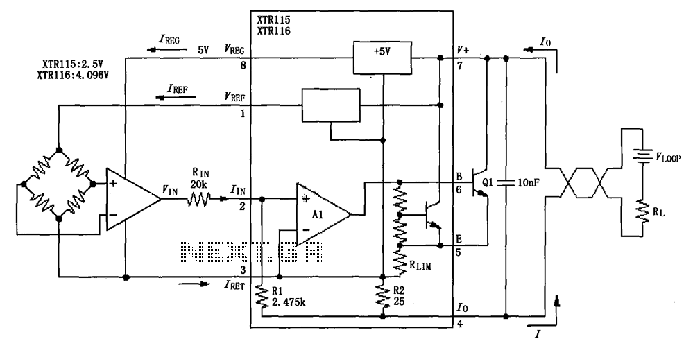
The output reference voltage VREF from the O pin is not utilized within the internal circuit; instead, it is provided to the external circuit. Similarly, the output voltage VREG is also supplied to the external circuit. All current return...
Schematic diagram. A presentation of the element-by-element relationship of all parts of a system. A schematic diagram serves as a crucial tool in electronic design and engineering, representing the interconnections and relationships between various components within a system. It provides...
Configured with capacitive coupling by inserting a small capacitor between the phototransistor and the bipolar transistor, this relay circuit will respond only to rapid changes. This relay circuit utilizes capacitive coupling to enhance its responsiveness to fast signal changes. The...