
schematic diagram graphic arts

A schematic diagram serves as a crucial tool in electronic design and engineering, representing the interconnections and relationships between various components within a system. It provides a visual framework that illustrates how each element, such as resistors, capacitors, transistors, and integrated circuits, interacts within the overall circuit.
In a typical schematic, symbols are used to denote different electronic components, and lines represent the electrical connections between them. This representation allows engineers and technicians to easily understand the functionality and layout of the circuit without the need for physical assembly.
Schematic diagrams are essential for troubleshooting, as they enable users to trace signals through the circuit and identify potential issues. Additionally, they serve as a reference during the manufacturing process, ensuring that all components are correctly placed and connected according to the design specifications.
The clarity of a schematic diagram is paramount; it should be organized logically, with components arranged to minimize confusion. Labels and values for each component are typically included to provide additional context, such as resistance values for resistors or capacitance for capacitors. By adhering to standardized symbols and conventions, schematic diagrams facilitate communication among engineers and ensure consistency across designs.
Overall, a well-crafted schematic diagram is an indispensable element in the development and documentation of electronic systems, enabling efficient design, analysis, and maintenance.schematic diagram. A presentation of the element-by-element relationship of all parts of a system.. 🔗 External reference
Related Circuits
Generating long delays of several hours can be accomplished by using a low frequency oscillator and a binary counter as shown below. A single Schmitt Trigger inverter stage (1/6 of 74HC14) is used as a squarewave oscillator to produce...
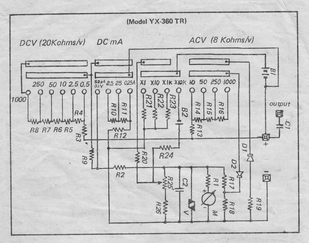
For individuals seeking a copy of the schematic diagram for this type of Analog Multitester, as well as other brands utilizing the same circuit diagram. The schematic diagram of an Analog Multitester typically features a variety of components arranged to...
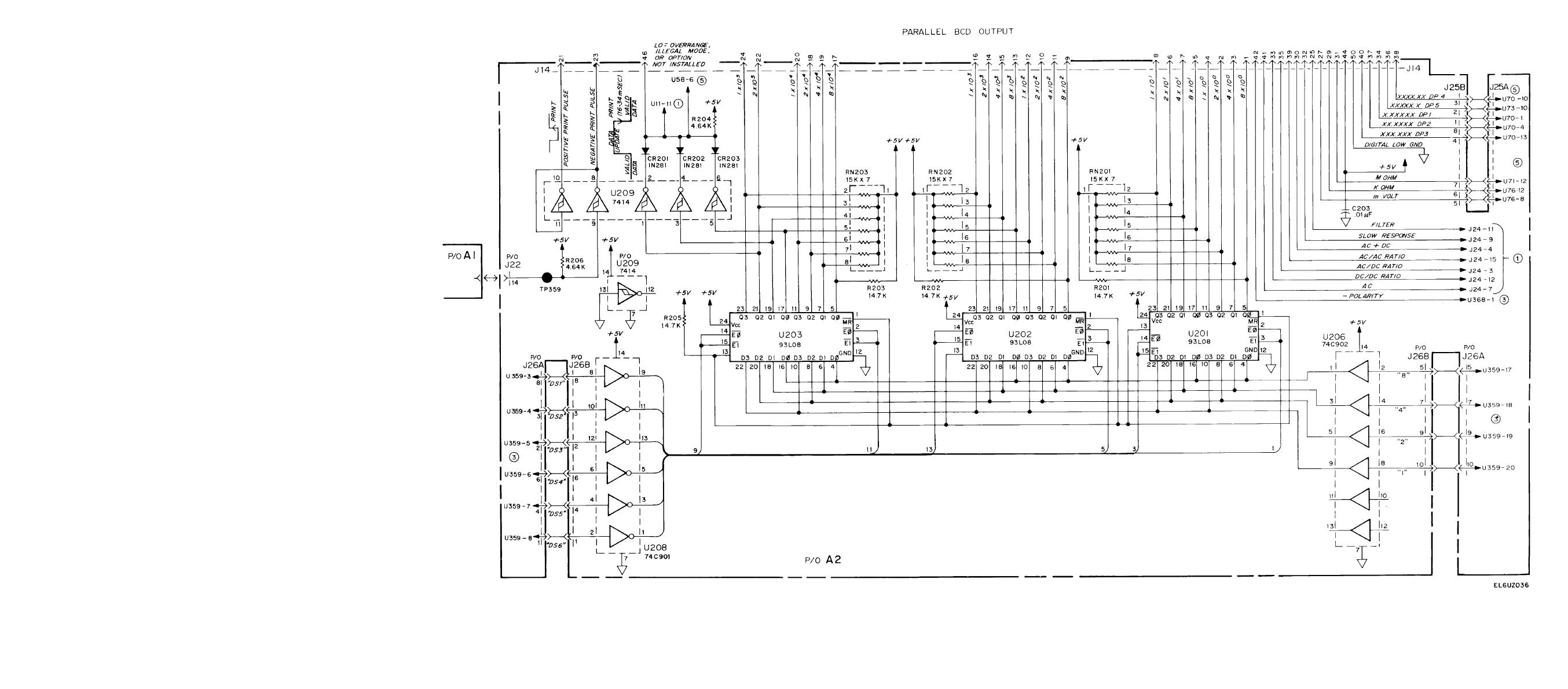
The definition of ecotherm insulation is crucial, particularly regarding its application in circuits. This includes the use of half adders in parallel adder configurations and the logic connection diagrams for parallel BCD (Binary-Coded Decimal) systems. A proper understanding of...
1999 Honda Civic Fuel Injector Wiring Diagram. The fuel injector wiring diagram for the 1999 Honda Civic outlines the electrical connections and components involved in the fuel injection system. This diagram is essential for troubleshooting and repairing issues related to...
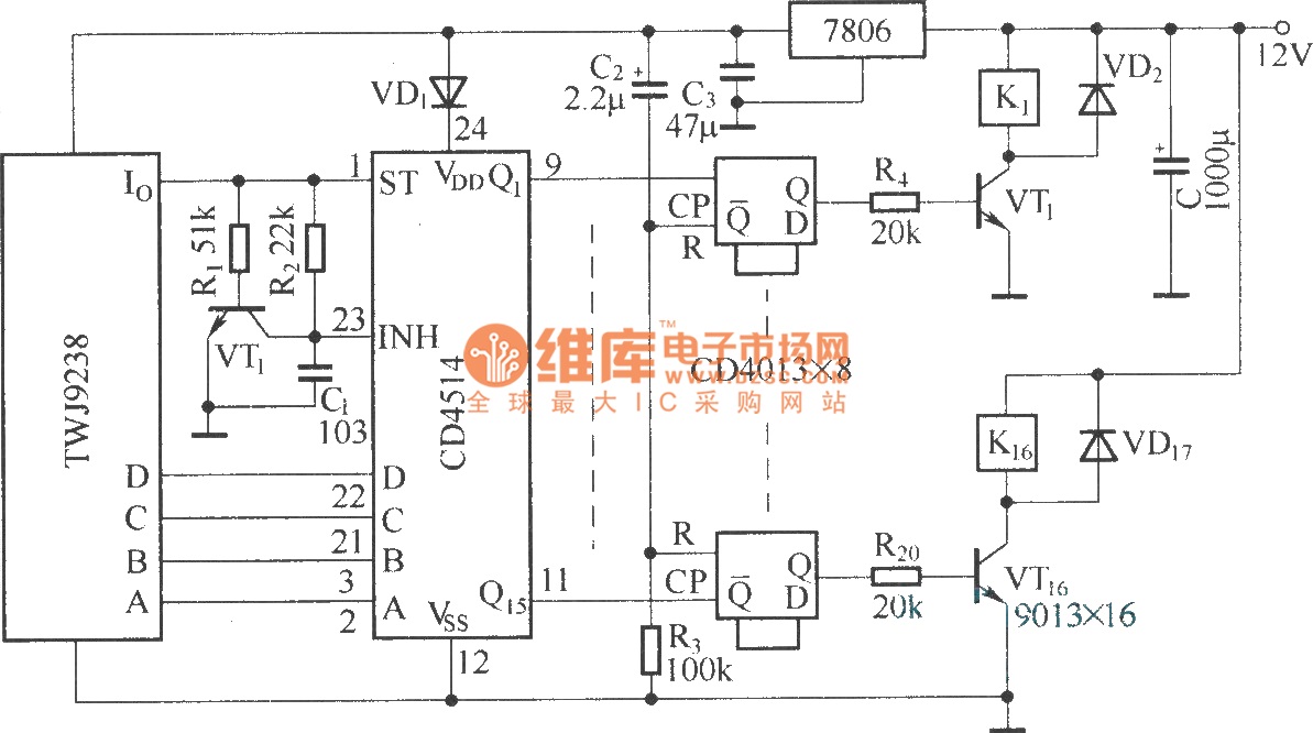
The Sixteenth Street control circuit consists of a secondary decoding output control circuit. Each output terminal of the sixteen decoding is connected to a bistable circuit made up of dual D flip-flops (CD4013). A DC relay is connected to...
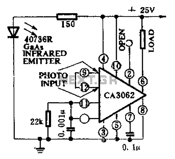
CA3062 is a combined photodetector and power amplifier that responds to the optical signal generated by the on/off output. The integrated circuit's transistor output saturation should be either on or off to prevent temperature rise in the silicon. When...