
simple FSK/AFSK Modulator

The AFSK modulation technique offers a practical solution for transmitting digital data over analog communication channels by leveraging audio tones. The circuit's design, which incorporates a single NOT gate, simplifies the implementation of FSK modulation, making it more accessible for various applications. The On Semiconductor NL27WZ14 inverter functions as the core component that converts TTL-level digital signals into frequency-modulated audio tones.
The oscillator output frequency of 2400 Hz serves as the baseline for the modulation process. The adjustment capability provided by resistor R1 allows for fine-tuning of the output frequency, ensuring compatibility with different transmission standards or requirements. When the TTL input signal is high, the introduction of a capacitor modifies the circuit's time constant, effectively reducing the frequency output. This characteristic allows for the generation of two distinct tones, facilitating the encoding of binary data.
The additional capability to operate at higher frequencies, such as 4800 Hz and 9600 Hz, by adjusting the timing capacitors C1 and C2, provides flexibility in communication applications. This feature is particularly advantageous in environments where bandwidth availability is a critical factor. The design's efficiency and compactness make it an attractive option for integration into various electronic systems that require reliable data transmission through audio signals. Overall, this AFSK modulator circuit exemplifies a streamlined approach to achieving frequency-shift keying suitable for modern communication needs.Audio frequency-shift keying (AFSK) is a modulation technique by which digital data is represented by changes in the frequency (pitch) of an audio tone, yielding an encoded signal suitable for transmission via radio or telephone. Normally, the transmitted audio alternates between two tones: one, the mark , represents a binary one; the other, the
space , represents a binary zero. Commercial FSK (frequency-Shift-keying) modulators are bulky and need many Passive components. the circuit uses a single NOT gate (inverter), On Semiconductor NL27WZ14 into a surface mount Package, to generate continuous FSK data from the TTL level signals. the Spending of this range are compatible with the available channels. If the TTL input is low, the circuit is a continuous execution of the oscillator output about 2400 Hz (adjustable with R1).
If the input assumes a high level of The oscillator frequency reduces by half with the Introduction of a capacitor in the circuit over time Q1. converter IC provides space for surgical Frequency of approximately 80 kHz. You can easily Operation of the FSK modulator at higher frequencies eg, 4800 and 9600 Hz, by reducing the values of the timing capacitors C1 and C2.
🔗 External reference
Related Circuits
This is a straightforward circuit designed for charging lead-acid batteries using the PB137 regulator. The PB137 is utilized in the lead-acid battery charger circuit due to its ability to provide... The PB137 voltage regulator is a linear regulator specifically suited...
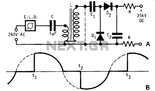
A light dimmer, a 1 µF capacitor, and a 12 V car ignition coil form a simple line-powered high-voltage generator. The current in the dimmer is illustrated in Fig. B. During the time intervals tp to t2, determined by...
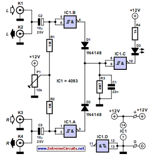
This audio peak detector enables the monitoring of a pair of stereo channels using a single LED. The circuitry employed for both the left and right channels is identical. The audio peak detector circuit is designed to provide a visual...
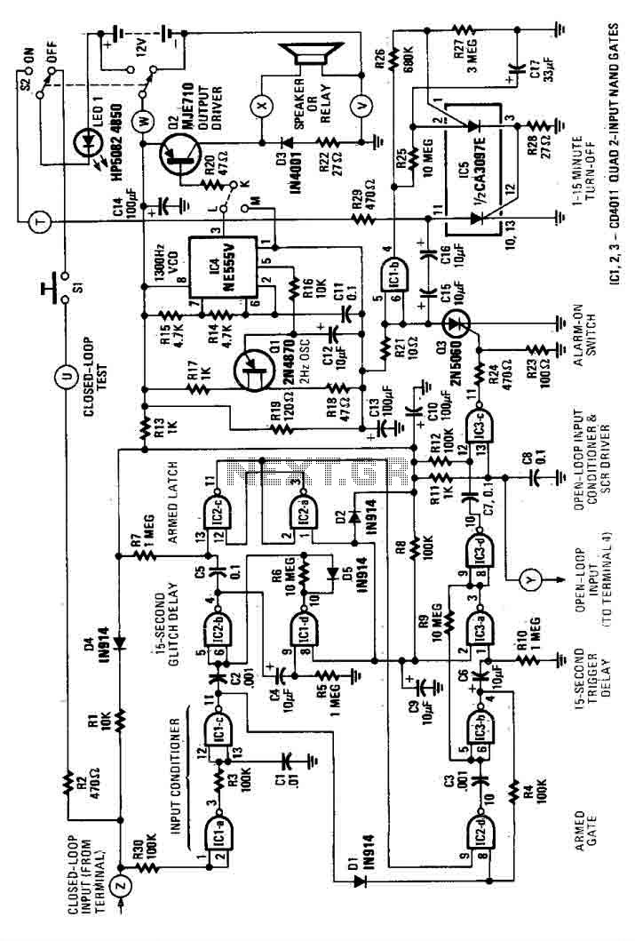
This house alarm circuit features both open and closed loop sensors and includes a self-shutdown function. The delay after triggering can be adjusted between 1 minute and 12 minutes, while the delay before triggering is set at 13 seconds....
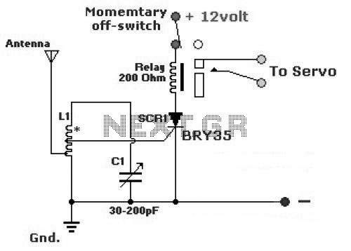
The diagram illustrates a simple and efficient receiver designed for controlling garage doors, starter motors, alarms, warning systems, and various other applications. The SCR utilized in this circuit features an exceptionally low trigger current of 30 µA. The circuit operates...
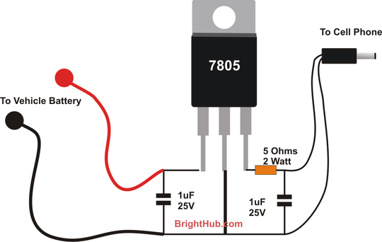
With the advent of modern integrated circuits (ICs), sophisticated circuits today are no longer required to be complex and lengthy. The chips themselves contain most of the intricate circuitry built-in and can independently perform the desired functions. For instance,...