
Simple high-volt supply

The circuit operates by utilizing the properties of a light dimmer, which effectively modulates the amount of power delivered to the load. The dimmer's internal triac acts as a switch that controls the timing of current flow to the capacitor and subsequently to the ignition coil. When the triac is triggered, it allows a pulse of current to flow through the primary winding of the ignition coil, inducing a magnetic field. The rapid change in current creates a high-voltage pulse in the secondary winding due to the principles of electromagnetic induction.
The capacitor, rated at 1 µF, serves as a charge storage element, accumulating energy during the brief periods when the triac is conducting. This energy is then released as a high-voltage pulse at the secondary of the coil. The frequency of operation, which is linked to the AC line frequency, contributes to the generation of high-voltage pulses at a rate consistent with the line frequency.
To convert the high-voltage alternating current (AC) output from the ignition coil into a usable high-voltage direct current (DC), a voltage doubler circuit is implemented. This circuit typically consists of two diodes (D1 and D2) and two capacitors. The selenium rectifiers are chosen for their reliability and efficiency in rectifying the high-voltage output, which is essential for applications such as powering television sets.
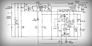
In addition to the rectification process, the inclusion of high-value output shock protection resistors is critical for safeguarding against potential high-voltage shocks. These resistors limit the current that can flow through the circuit during fault conditions, enhancing the overall safety of the high-voltage generator setup. Proper selection of resistor values and ratings is essential to ensure effective protection while maintaining the desired performance of the high-voltage output.A light dimmer, a 1 µf capacitor and a 12 V car ignition coil form the simple line powered HV generator. The current in the dimmer is shown in Fig. B. At times tp t2, set by the dimmer switch, the inner triac of the dimmer switches on, and a very high and very fast current pulse charges the capacitor through the primary of the induction coil.
Then at a rate of 120 times per second for a 60 Hz line, a very high voltage pulse appears at the secondary of the coil. To obtain an HV dc output, use a voltage doubler. Dl and D2 are selenium rectifiers (TV 18 Siemens or ITT) used for the supply of television sets. High value output shock protection resistors, R, are recommended when suitable.
Related Circuits
This is a power supply circuit that produces a voltage range of 12 to 24 V. It is straightforward, requiring only a bridge rectifier, a filter capacitor, and a transformer, without the need for a regulator. A bridge rectifier...
This is a low voltage, high-current output switching DC power supply with an input of 220 volts AC. In this circuit, an ST2 DIAC relaxation oscillator, Q3, C1, and the DIAC initiate conduction of the output switching transistor Q1....
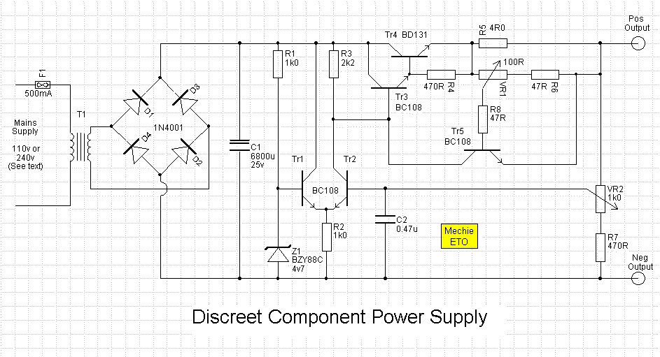
An error amplifier is constructed using transistors Tr1 and Tr2, configured as a differential amplifier, commonly referred to as a long-tailed pair, with the collector leads being a notable feature. One input of this differential amplifier is sourced from...
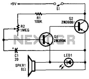
Two complementary transistors create a basic oscillator with a frequency range of approximately 0.5 to several Hz. This circuit serves as a metronome, timer, or pacer for exercise equipment. The oscillator circuit utilizes a pair of complementary transistors, typically one...
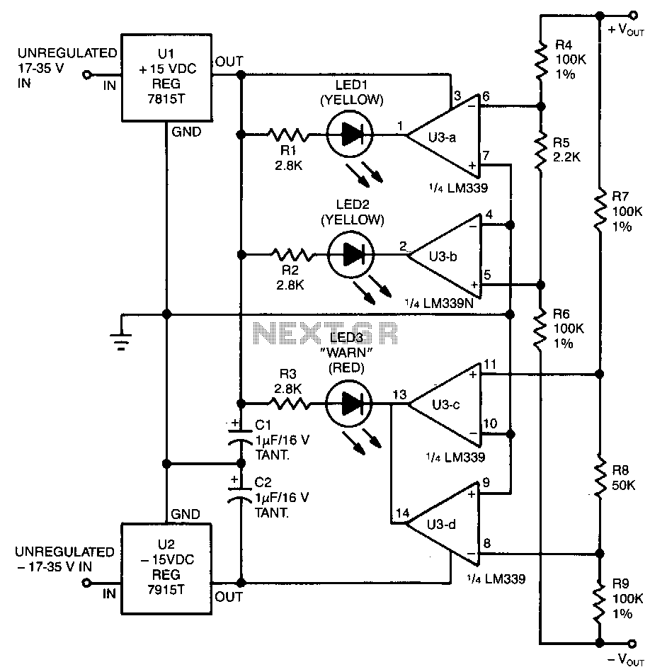
This circuit utilizes two pairs of comparators from an LM339N quad comparator. One pair controls the yellow positive (+) and negative (-) indicators, while the other pair drives the red warning LED3. The circuit is powered by the unregulated...
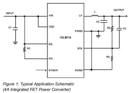
Utilizing Integrated Switching Regulators in Power Supply Design Engineers often find themselves pondering where to begin when designing power supplies. Key decisions must be made regarding... Integrated switching regulators are critical components in modern power supply design, offering efficient voltage...