
this circuit is isp flash programmer
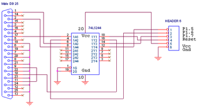
This circuit serves as a foundational interface for programming and communication with ATMEL microcontrollers, particularly the AT89Sxx and ATMEGA series. The primary signals involved in this circuit are MISO (Master In Slave Out), MOSI (Master Out Slave In), SCK (Serial Clock), and RESET, which are essential for synchronous serial communication.
The MISO line is used to transmit data from the microcontroller to the master device, while the MOSI line carries data from the master to the microcontroller. The SCK line provides the clock signal that synchronizes data transmission between the master and the microcontroller. The RESET line is crucial for initializing the microcontroller, ensuring it starts executing code from the beginning of its memory.
In practical applications, this circuit can be implemented for various purposes, including programming the microcontroller during development or enabling communication between the microcontroller and other devices in an embedded system. The circuit may include pull-up resistors on the RESET line to ensure reliable operation, as well as decoupling capacitors to stabilize the power supply voltage.
Overall, this circuit is integral to leveraging the capabilities of ATMEL microcontrollers, facilitating both development and operational functionality in electronic systems.This circuit is used on the ATMEL Microcontroller IC. However, the circuit is used for Microcontroller AT89Sxx. and ATMEGA xxx if you know about MISO, MOSI, SCK AND RESET 🔗 External reference
Related Circuits
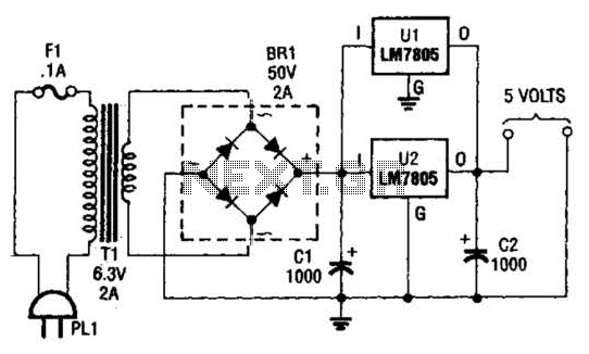
This DC supply is excellent for operating battery-powered antique radios, as it is designed to prevent damage to the tube filaments. The circuit is useful for powering the filaments of 00-A, 01-A, 112A, and 71A tubes, which require 5V...
This circuit sequentially lights ten bulbs, first in one direction and then in the opposite direction, creating an appealing visual effect. Gates N1 and N2 form an oscillator, which serves as a clock for the BCD up/down counter CD4510...

A 100W amplifier with a frequency range from DC to 500KHz features a photoelectric starting operational amplifier with high input impedance and high gain characteristics, enabling transformerless output power of 100W. The load current can reach up to 10A,...
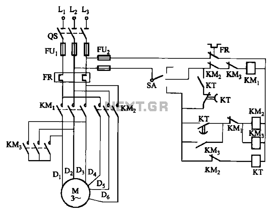
The circuit depicted in Figure 3-98 demonstrates how motor starting and low-speed operation are managed using switch SA. By adjusting the time relay KT, the motor's operation can transition from low speed to high-speed operation within a specified time...
The Mark3 version of the Infrared extender is specifically designed to control appliances that utilize high-frequency modulated infrared remote signals. The Mark3 Infrared extender functions as a bridge between a standard infrared remote control and appliances that operate with high-frequency...

This simple circuit can create an 18 LED flasher to decorate a Christmas tree. The white, blue, and red LEDs flash at different rates to provide a colorful display. It is a light-sensitive circuit, automatically activating in the evening...