
wireless temperature sensor
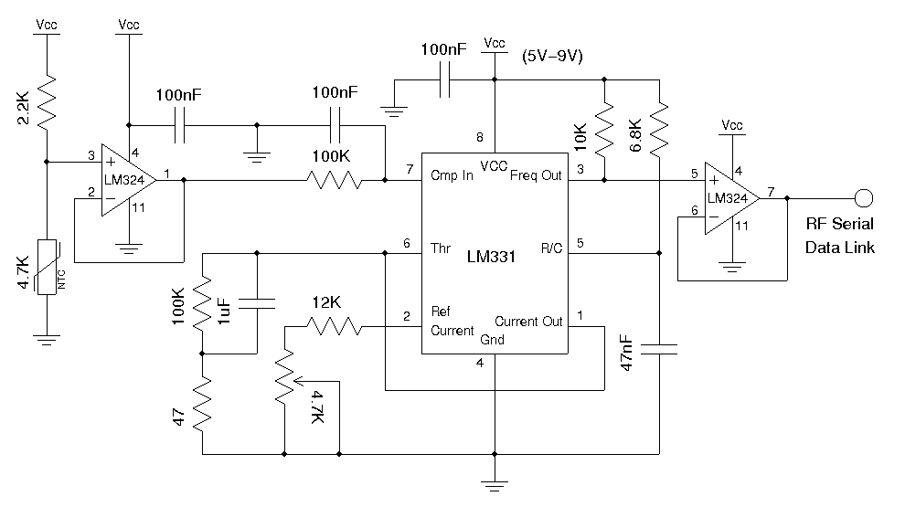
The circuit employs a 1/4 LM324 (or LM2902) as a voltage follower to buffer the input voltage from the resistor-thermistor voltage divider. The output from the voltage divider is then fed into an LM331 voltage-to-frequency converter. The LM331 configuration is based on a reference design. The capacitor connected to pin 5 must be adjusted to ensure that the maximum frequency output from the oscillator remains below the maximum bit rates supported by the RF link. The RF data transmitter utilized has a maximum bit rate of 2400 bps, leading to the selection of a 47nF capacitor, resulting in an oscillation frequency of approximately 700 Hz at room temperature. The frequency output from the LM331 is buffered again through another 1/4 LM324 (or LM2902) before being sent to the RF data link transmitter. Although this voltage-to-frequency circuit may not offer the highest accuracy, it suffices for the temperature measurement application discussed here. The LM331 datasheet emphasizes that the timing components must possess high stability to achieve a high level of accuracy and to minimize frequency drift. The completed transmitter section of the temperature sensor is illustrated above. It is crucial to have a regulated power supply to obtain accurate readings, as the readings are referenced by the thermistor voltage divider.
An alternative design could have involved using another LM331 as a frequency-to-voltage converter, with the voltage readouts utilized to compute temperature readings. However, this would necessitate an A/D converter to convert the signal back to digital form for calculations. To simplify the design, an Arduino MCU (ATmega328) is used to measure the frequency output directly from the RF data link receiver. The setup at the receiver end is depicted in the following illustration. Once both the transmitter and receiver are operational, conversion of the received frequency readings back to temperature readings is required. A reference schematic is provided to clarify the calculation process.
The circuit begins with an analog temperature sensor, which can be a thermistor or an LM335. The sensor output is connected to a resistor to form a voltage divider, producing a variable voltage that corresponds to the temperature. This voltage is buffered by one section of the LM324 or LM2902 operational amplifier, ensuring that the impedance seen by the voltage divider remains consistent, preventing loading effects that could alter the voltage reading.
The buffered voltage is then sent to the LM331 voltage-to-frequency converter. The LM331 converts the analog voltage signal into a frequency output, where the frequency is proportional to the input voltage. The adjustment of the capacitor at pin 5 is critical, as it determines the maximum frequency output. This frequency is then buffered again using another section of the LM324 or LM2902 to ensure that the signal is strong enough for transmission through the RF module.
The RF data transmitter modulates the frequency signal for wireless transmission. The choice of a 47nF capacitor is made to keep the output frequency within the limits of the RF module's maximum bit rate. This design allows for effective temperature monitoring without the need for complex digital processing at the transmitter side.
At the receiver end, the Arduino MCU measures the frequency output from the RF data link. The MCU is programmed to interpret the frequency and convert it back to a temperature reading using the known relationship between the input voltage to the LM331 and the output frequency. This approach simplifies the design while maintaining sufficient accuracy for temperature measurement applications. The overall system is designed to be straightforward, efficient, and effective for remote temperature monitoring.Use a voltage to frequency conversion chip along with an analog temperature sensor such as LM335 or a thermistor, and then transmit the modulated frequency signal via an RF data link module. Alternatively, we can use a digital temperature sensor and sending the sensor readings over RF serial data link digitally.
In this post I will stick with the first approach. Here the 1/4 LM324 (or LM2902) forms a voltage follower to buffer the input voltage from the resistor-thermistor voltage divider, and the divider output is fed into an LM331 voltage to frequency converter. The LM331 portion of the circuit was taken directly from the reference design. The capacitor at pin 5 needs to be adjusted so that the maximum frequency output from the oscillator is below the maximum bit rates supported by the RF link.
The RF data transmitter I used has a maximum bit rate of 2400 bps and thus I used a 47nF capacitor and the oscillation frequency is around 700 Hz under room temperature. The frequency output from LM331 is again buffered via another 1/4 LM324 (or LM2902) before feeding into the RF data link transmitter.
This voltage to frequency circuit is arguably not the most accurate one and you could improve your accuracy by adding an op-amp integrator as illustrated in the datasheet, but for the temperature measurement application we are discussing here, this simple circuit is accurate enough. According to the LM331 data sheet, the timing components need to have very high stability in order to achieve a high level of accuracy and minimize frequency drift.
The picture above shows the finished transmitter portion of the temperature sensor. Note that the power supply must be regulated in order to obtain accurate readings since it is referenced by the thermistor voltage divider. I could have built the receiver using another LM331 as a frequency to voltage converter and use the voltage readouts to calculate the temperature readings.
But then I would need to use an A/D converter to convert the signal back to digital form in order to perform the calculation. To simplify the design, I used an Arduino MCU (ATmega328) to measure the frequency output from the RF data link receiver directly.
The following picture shows the setup on the receiver end. With the transmitter and receiver working, now we need to convert the received frequency readings back to the temperature readings. Again, to help you understand how the calculation is done I have included the reference schematic below:
🔗 External reference
Related Circuits
The AD592 is a two-terminal monolithic integrated circuit temperature transducer that produces an output current proportional to absolute temperature. It functions as a high-impedance temperature-dependent current source of 1 µA/K across a wide range of supply voltages. Enhanced design...
With the help of a simple ceramic piezoelectric detector, it is possible to assemble an interesting and useful impact sensor unit, which can be used to detect... An impact sensor unit utilizing a ceramic piezoelectric detector operates by converting mechanical...
The objective is to add a security sensor light near the main entrance that operates on 12 volts. While 12-volt PIR sensors are available, they tend to be costly, often exceeding $50 each and are specifically designed for security...
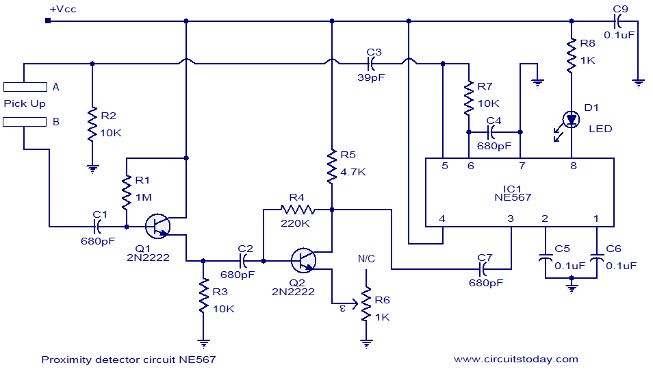
A simple proximity detector circuit utilizing the NE567 integrated circuit (IC). The circuit activates an LED when an object approaches the sensor. The NE567 is a versatile phase-locked loop (PLL) device commonly used for applications such as proximity detection due...
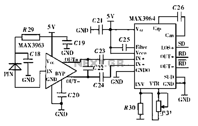
Ethernet is the most widely used networking technology, known for its high reliability, informative media, and ease of expansion and updates. It is commonly utilized in businesses, schools, and various other fields. According to the IEEE802.3 Ethernet specification, the...
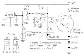
The following circuit illustrates the use of a 741 operational amplifier (op-amp) in a constant temperature control circuit diagram. It is designed to reduce the drift of a Ramsey FM10a. The circuit employs the 741 op-amp, which is a general-purpose...