
741 IC For Constant Temperature Control

The circuit employs the 741 op-amp, which is a general-purpose operational amplifier known for its versatility in various applications, including temperature control. The constant temperature control circuit is crucial for maintaining stable operating conditions in sensitive electronic components, such as those found in the Ramsey FM10a, which is a frequency modulation transmitter.
In this configuration, the 741 op-amp is typically used in a feedback arrangement to compare the actual temperature with a reference temperature set by a thermistor or a temperature sensor. The output of the op-amp drives a heating element or a cooling device to adjust the temperature accordingly, ensuring that it remains constant despite external fluctuations.
The circuit may include resistors and capacitors to stabilize the feedback loop and filter out noise, thereby enhancing the accuracy of the temperature control. Additionally, the use of a potentiometer allows for fine-tuning of the reference temperature, providing flexibility in the circuit's application.
Overall, the integration of the 741 op-amp in this constant temperature control circuit exemplifies the importance of operational amplifiers in maintaining precise control in electronic systems, thereby improving the reliability and performance of devices like the Ramsey FM10a.The following circuit shows about 741 IC For Constant Temperature Control Circuit Diagram. Features: used to lower the drift of a Ramsey FM10a . 🔗 External reference
Related Circuits
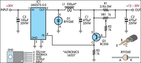
Operating a stepper motor with a fixed (constant) voltage supply leads to inadequate torque at high speeds, often causing the motor to stall at relatively low speeds. To address this issue, various solutions can be implemented, one of which...
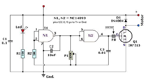
A quad 2-input NAND Schmitt trigger circuit can be designed using the MC14093 CMOS type IC, which serves as a simple pulse width modulation (PWM) controller electronic project. This PWM controller is straightforward and requires only a few external...

This is the power diagram for motor forward and reverse operation. To change the motor direction, one polarity must be altered, for example, changing R to S. For detailed information, please refer to the following. The described power diagram illustrates...
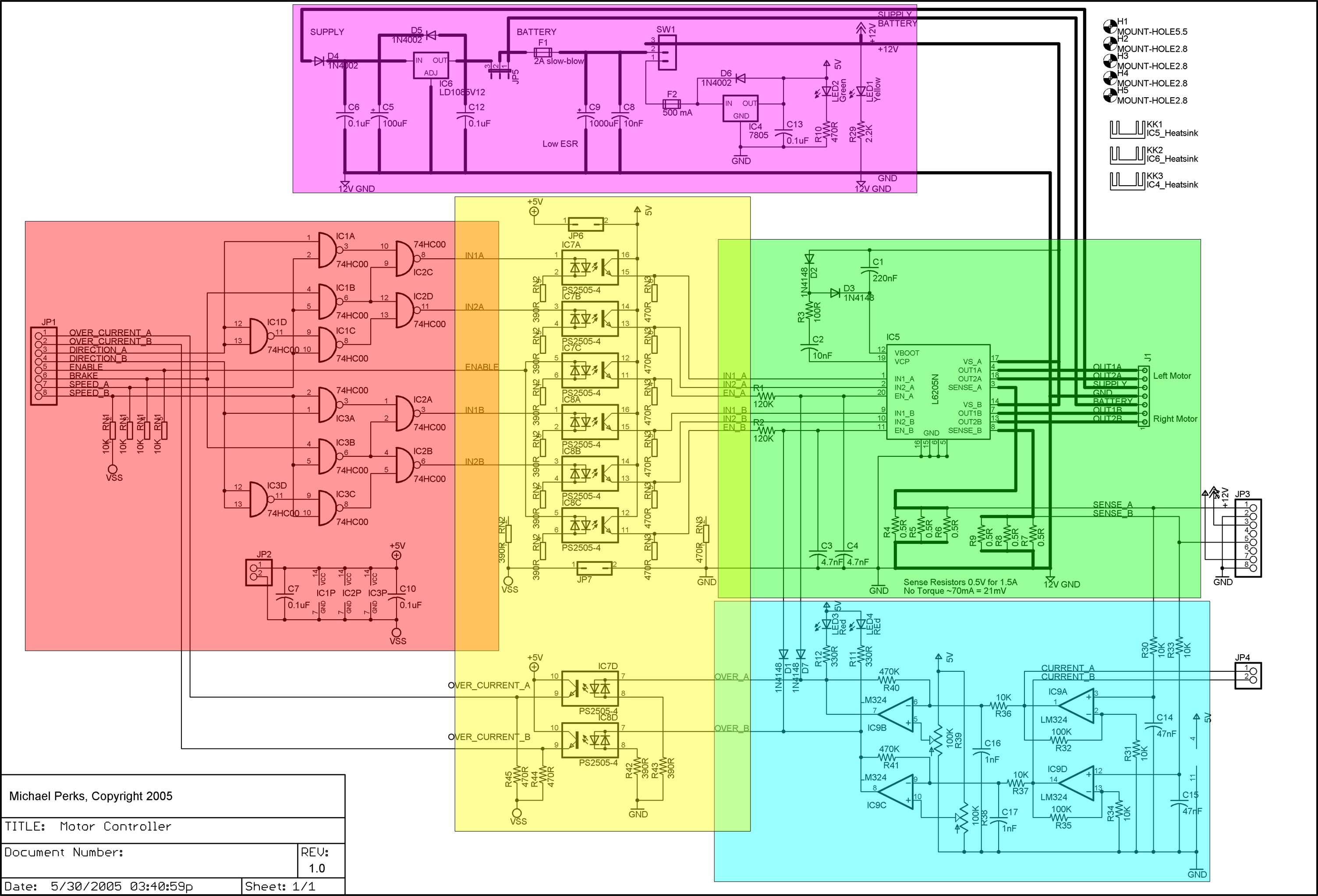
A dual DC motor controller employs an H-bridge controller chip. In addition to the standard features of the H-bridge driver chip, such as thermal and over-current protection, the circuit supports dual 12V/5V regulated power supplies, sign/magnitude and brake driver...
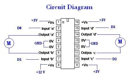
A remote Sun SPOT will transmit data to a Sun SPOT mounted on a car, which will control an integrated circuit (IC) according to the digital input/output pins D0 to D3. The IC will subsequently drive the motors that...
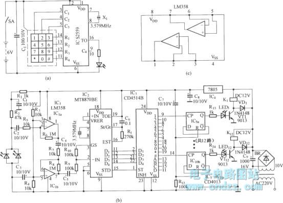
Figure (a) illustrates an infrared emission circuit composed of a 12-key keyboard and an S2559. Figure (b) displays a DTMF decoder circuit along with a channel control circuit utilizing the MT8870. Figure (c) presents a voltage amplifier circuit constructed...