
Clap-Controlled Switch

The circuit operates by utilizing an electret microphone, which serves as the primary sensor for detecting sound, specifically the sound of handclaps. When a handclap occurs, the microphone converts the acoustic signal into an electrical signal. This signal is then processed by an amplifier stage to enhance its strength and clarity, ensuring that even faint claps can trigger the system.
The output from the amplifier is fed into a microcontroller or a dedicated sound detection circuit, which is programmed to recognize the distinct pattern of rapid clapping. The microcontroller analyzes the input signal and determines when the threshold for a 'clap' has been met. Once the required number of claps is detected within a specific timeframe, the microcontroller sends a signal to a relay or transistor switch.
The relay or transistor acts as the control element for the devices being switched. When activated, it can turn on or off multiple devices, such as lights or appliances, depending on the configuration of the circuit. This allows for versatile applications in home automation or interactive installations.
Power supply considerations for the circuit include ensuring that the electret microphone, amplifier, microcontroller, and output devices all operate within their specified voltage and current ratings. A suitable power source, such as a battery or an AC adapter, should be employed to provide stable operation.
In summary, this handclap-activated circuit provides a convenient and innovative method for controlling multiple devices through simple sound detection, making it an engaging solution for various electronic applications.This circuit can switch two or more devices on and off in response to a series of rapid handclaps. The claps are picked up by an electret microphone and a.. 🔗 External reference
Related Circuits
This contributed project is a result of considerable collaboration between Sergio and myself, and should not be seen as necessarily a complete project in itself, but a stepping stone to understanding switching power supplies, how they work, and what...
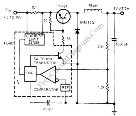
Switching voltage regulator utilizing the TL497 integrated circuit, achieving up to 75% efficiency. The output voltage is 5V, while the input voltage ranges from 7.5V to 15V. The TL497 is a versatile integrated circuit designed for use in switching voltage...
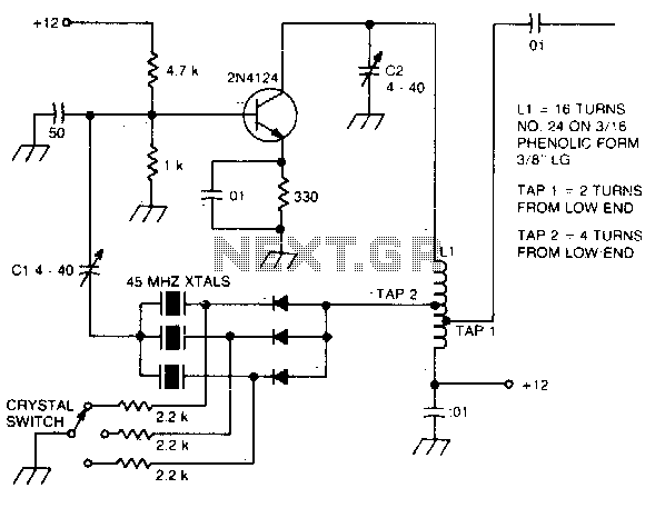
The large inductive phase shift of LI is compensated for by Cl. Overtone crystals have very narrow bandwidth; therefore, the trimmer has a smaller effect than for fundamental-mode operation. The statement discusses the compensation of inductive phase shifts in a...
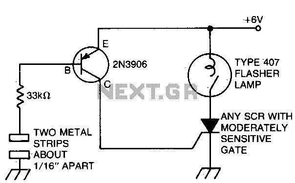
The battery-powered light activates with ease, remaining illuminated for a few seconds before automatically shutting off. The circuit is engaged when a finger bridges the gap between two metal strips, approximately 1/16 inch apart. Sufficient current flows through the...
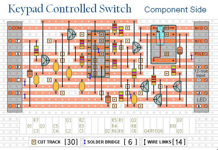
This is a universal version of the four-digit alarm control keypad. The design has been modified to free up the relay contacts, enabling the circuit to function as a general-purpose switch. A single pole changeover (SPCO) or single pole...
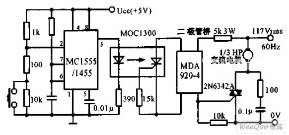
The switch shut-off time delay circuit consists of a timer, optocouplers, a bridge SCR, and an SCR AC switch. When the control button is released, it allows the motor or other AC power to remain active for one hour....