
The switch shut off time delay circuit diagram

The switch shut-off time delay circuit is designed to control the duration for which an AC load remains energized after a control button is released. The core components include a timer IC that governs the time delay, optocouplers for isolation and signal transfer, and a bridge SCR configuration that facilitates the control of AC loads.
When the control button is pressed, the circuit is powered, and the timer begins its countdown. The voltage at pin 2 is reduced to one-third of the supply voltage (Ucc/3), which is essential for the operation of the timer. As the timer counts down, the output at pin 3 transitions from a low to a high state, which activates the LED indicator, providing visual feedback that the circuit is operating.
The optocouplers serve to isolate the control logic from the high-voltage AC side, ensuring safety and preventing damage to sensitive components. The bridge SCR is employed to handle the AC switching, allowing for the control of high-power loads without mechanical switches. This arrangement not only enhances durability but also minimizes wear and tear on components.
Once the timer completes its countdown, the output at pin 3 will drop, turning off the LED and deactivating the SCR, which in turn cuts off the AC power to the load. This design is particularly useful in applications where a delayed shut-off is required, such as in motor control, lighting systems, or other automated processes where a temporary delay is beneficial. The entire circuit can be powered from a standard AC source, and with appropriate component selection, it can be tailored for various load requirements and time delays.The switch shut off time delay circuit is shown as below. The switch shut off time delay circuit is composed of the timer, optocouplers, bridge SCR, SCR AC switch. When the control button is released, the keeping motor or other AC start power for 1 hour. Button closure. 2 pin voltage step-down Ucc / 3 below. The output pin 3 rises. LED lights. The bridge S.. 🔗 External reference
Related Circuits
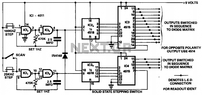
This circuit was designed to ensure safe operation of a 48-channel mobile transceiver while in motion. It incorporates oscillators that facilitate single-stepping or scanning functions. The scanning feature enables the user to sequentially check all 48 channels for occupancy,...
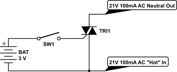
Control a furnace using a 3.3V microcontroller. The furnace operates by connecting a common 21V AC "hot" line to one of two AC "neutral" output lines: Fan and Heat. When connected, they have relatively low current flow, approximately 100mA....
There are numerous circuits designed for low voltage regulators. However, for higher voltages, such as those required for valve circuits, the approach differs. This is the reason for the design of a simple regulator capable of handling these voltages....
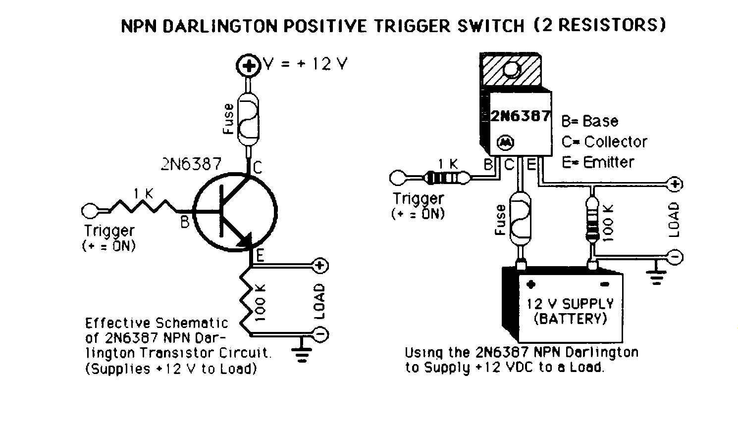
Mechanical 12 Volt DC automotive relays are commonly used in the car audio industry to activate amplifiers, lock doors, and roll up windows. However, solid-state switches provide an alternative method for activating these loads. The reliance on mechanical relays,...
A second RM output and a sync input have been added to the 555 timer circuit. The sync input is derived from one of Rene Schmitz's voltage-controlled oscillators (VCOs). There are two transistors in the PCB images that lack...
The two circuits demonstrate the operation of opening a relay contact shortly after the ignition or light switch is turned off. The capacitor becomes charged, and the relay remains closed until the voltage at the diode anode reaches 12...