
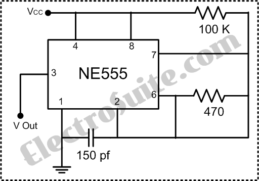
clock Crystal circuit works in breadboard but not in perfboard

The circuit in question appears to be a simple LED blinking circuit, likely utilizing a 555 timer or a similar astable multivibrator configuration. The discrepancy in blinking frequency between the breadboard and perfboard could be attributed to several factors, including variations in capacitance due to the use of different components, soldering issues leading to unintended connections, or differences in the layout affecting the circuit's performance.
In a typical 555 timer circuit, the blinking frequency is determined by the resistors and capacitors used. The formula for the frequency (f) of the blinking LED is given by:
\[ f = \frac{1.44}{(R1 + 2R2) \times C} \]
where R1 and R2 are the resistances in ohms, and C is the capacitance in farads. If the capacitors have been changed from 15 pF to 22 pF, it is essential to recalculate the expected frequency to confirm that it aligns with the observed behavior.
Furthermore, soldering on a perfboard introduces potential issues such as cold solder joints, bridging, or unintentional shorts, which can alter the circuit's characteristics. It is advisable to inspect the solder joints closely and ensure that there are no unintended connections between adjacent pads. Additionally, the layout of the perfboard may introduce parasitic capacitance or inductance, which could affect the timing characteristics of the circuit.
To troubleshoot the issue, it is recommended to:
1. Reassess the component values and ensure they are correctly rated and functioning.
2. Double-check all solder joints for quality and integrity, ensuring no shorts or cold joints exist.
3. If possible, utilize a multimeter to measure the resistances and capacitances in the circuit to confirm they match the expected values.
4. Consider using a different perfboard or layout to minimize potential interference from parasitic elements.
These steps may help diagnose the cause of the unexpected blinking frequency when transitioning from breadboard to perfboard.It works perfectly on the breadboard, where I can see the LED blinking at 2 Hz. However, when I try to solder it on the perfboard, it blinks much faster. I don`t have a way to measure, but I`d say something like 10 Hz. I tried to mount three times on the breadboard and three times on the perfboard, and always get the same result. I checked and rechecked the connections, and everything seems to be fine. I have no idea where the problem might be. What could be wrong I tried replacing the two 15pF capacitor for two 22pF, but it didn`t help. Unfortunately, I don`t have access to a oscilloscope to see what`s happening inside. The second one is the soldering side. Please excuse my bad soldering, I`m a beginner, and it`s a little messy from all soldering/desoldering. However, I tested all connections and the connections are correct. 🔗 External reference
Related Circuits
More: The input data lacks specific content, providing only placeholders without any detailed information. In the context of electronic schematics, a comprehensive description typically involves detailing the components, their interconnections, and the overall functionality of the circuit....
The safe 12V car adapter described here can be used to limit the current from a +12 volt car battery, available from the in-dash cigar lighter power port, to below 2.6A. The 12V car adapter is designed to ensure that...
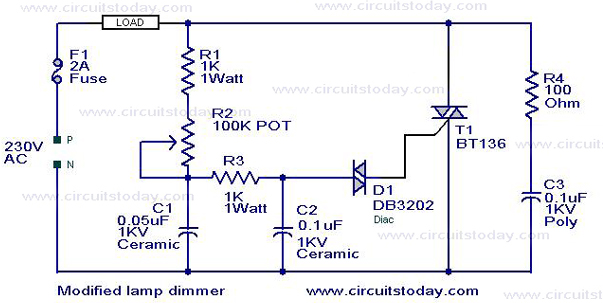
This is a modification of the Simple Lamp Dimmer/Fan Regulator circuit that was previously posted. The operation of the circuit remains the same as the original; however, it now includes a snubber circuit composed of resistor R4 and capacitor...
The 60 Hz frequency generator circuit is essential for creating inverters or hardware related to AC current voltage. This 60 Hz frequency generator is straightforward and highly accurate, producing a precision square wave output. The core of this generator...
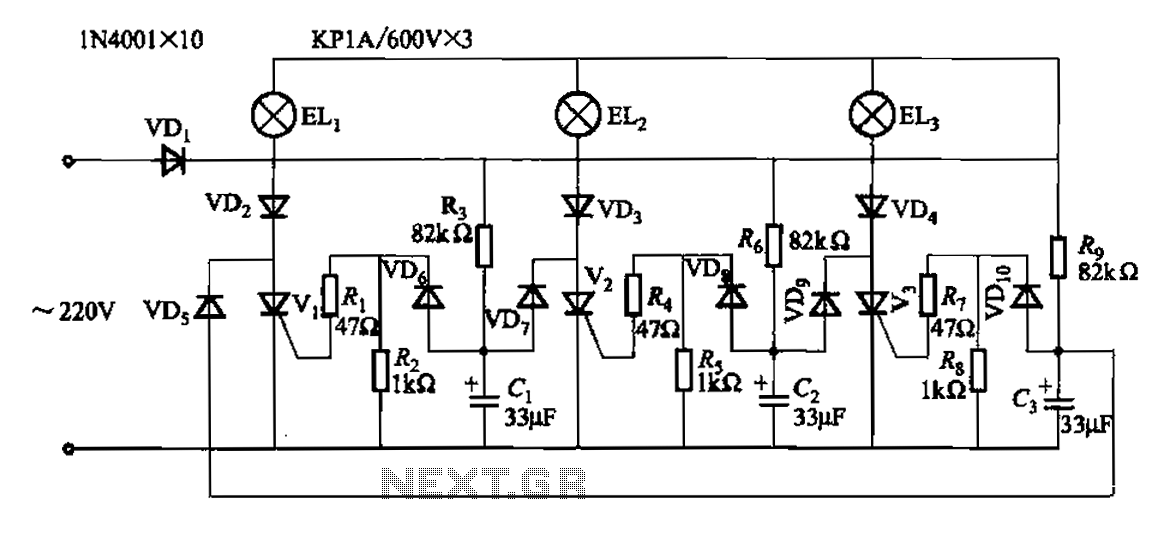
The circuit operates with a 220V mains supply through a diode (VDi) configured as a half-wave rectifier. Capacitors C1 to C3 are charged, and due to the lack of full synchronization in the charging process, a pilot thyristor is...
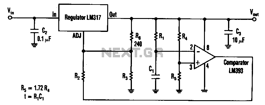
The timed two-voltage circuit can start and run a small DC motor or solenoid. The input voltage to the LM317 three-terminal regulator ranges from 5 to 40 V, and the output voltage can range from 2 to 36 V....