
Light Dimmer Circuit TRIAC dimmer circuitCircuitWorking

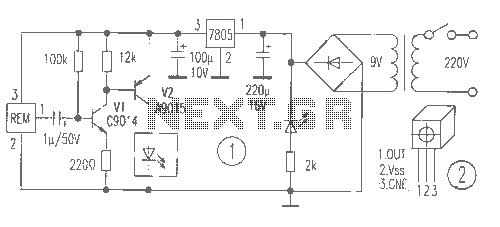
The modified circuit retains the fundamental operation of the original lamp dimmer and fan regulator design, allowing for variable control of the load. The addition of the snubber circuit serves a crucial role in managing voltage transients that can occur during the switching operations of the triac. The resistor R4 and capacitor C3 work together to suppress high-frequency noise and prevent voltage spikes, thereby enhancing the reliability and longevity of the triac T1.
The inclusion of a fuse in the circuit design is a significant safety feature. It provides overcurrent protection, ensuring that in the event of a fault or overload, the circuit will be interrupted, preventing potential damage to the components and reducing the risk of fire hazards. The selection of an appropriately rated fuse is essential to ensure that it operates effectively without nuisance tripping during normal operation.
Overall, this modified circuit presents a robust solution for controlling lamps and fans, integrating safety and performance improvements that enhance its practical application in various settings. Proper component selection and layout are critical to achieving optimal performance and safety standards in the final implementation of this circuit.This is a modification of the circuit Simple Lamp Dimmer/Fan Regulator previously posted here. The working of the circuit is same as that of the previous, but in addition a snubber circuit consisting of resistor R4 and capacitor C3 is included to improve the performance of the triac T1. A fuse is also included for better safety. I think this is t he better circuit to try. 🔗 External reference
Related Circuits

This is a design circuit for a low-cost FM antenna booster that can be used to listen to programs from distant FM stations clearly. The antenna FM booster circuit comprises a common-emitter tuned RF preamplifier wired around the VHF/UHF...
The following circuit illustrates the connection of the Devantech SRF04 Ultrasonic Sensor to the SV203 powered PPRK Circuit Diagram. This circuit is based on the Devantech SRF04 sensor and features a minimum initiation time of 10 milliseconds for the...
This is a simple game circuit designed for multiplayer enjoyment. The objective is to score one hundred points within a limited timeframe. To restart the game, the S1 button switch must be pressed. It is important to ensure that...

A voltage-controlled oscillator (VCO) operates similarly to a voltage-to-frequency converter (VFC). Its output frequency is determined by a control voltage input. In the circuit diagram, 'd' represents the amplifier input voltage, which is set to 0.6V, while 'h' denotes...
The receiver provides two TV signals, one for the living room and another for the bedroom, along with a satellite receiver. Watching television in the bedroom is convenient in Taiwan; however, when watching television in the living room, it...
The circuit was originally available in kit form from a surplus supplier, but it is likely more widely accessible now. It introduces innovative concepts such as utilizing a 555 timer as a pulse width modulator (PWM) and employing serial/parallel...