
Cloth from idling stop saving circuit

The female textile machine power control circuit is designed to manage the operation of a motor in a textile machine through a series of interconnected components. The primary elements include TRIACs (VTH1-VTH3) which act as electronic switches to control the flow of current to the motor. The absorption line, composed of resistors (R) and capacitors (C), is utilized to mitigate voltage spikes and ensure stable operation of the TRIACs.
The triggering current limiting resistor (Rz) is crucial for protecting the circuit from excessive current that could potentially damage the TRIACs or other components. K1 and K2 are reed switches that facilitate the control of the motor's operation. K1 initiates the motor's operation when the clutch lever is engaged, while K2 serves as a safety mechanism to stop the motor when the lever is disengaged.
The circuit is powered by a three-phase supply (L1, L2, L3), which is essential for providing sufficient power to the motor (M). The operation begins when the clutch lever is pushed into the Y1 position, which activates K1. This action allows VTH1-VTH3 to conduct, thereby energizing the motor and enabling it to run.
For stopping the motor, the clutch lever is moved to a position near the magnetic reed switch K2, which opens its normally closed contacts. This action interrupts the triggering signals to the TRIACs, leading to their deactivation and subsequently halting the motor.
This circuit design is critical for ensuring efficient operation and safety in textile machinery, providing both control and protection for the motor and associated components.Female textile machine power control circuit shown in a diagram, VTH1-VTH3 is TRIAC, R, and C is the absorption line, Rz is triggering the current limiting resistor, Kl is to s tart reed. K2 is the first stop Reed, Yl, Y2 is a magnet. Three-phase power Ll, L2, L3 through V th1 - VTH3 applied to the motor M on. Moving the clutch lever, the push to boot Yl position, Kl internal contacts connected, VTH1-VTH3 touch made conducting, energizing the motor M is running; shutdown, mounted on the clutch lever from the stop near the magnetic J Y2 K2, K2 inside the normally closed contacts break l open. Trigger off go the same way, VTH1 ~ VTH3 have been turned off, the motor M is stopped,
Related Circuits
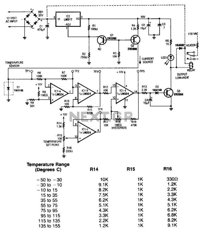
The LM35 temperature sensor outputs 10 mV/C for each degree Celsius above 0°C. At 20°C, the output voltage is calculated as 20 × 10 = 200 mV. The circuit consumes minimal power. Additionally, the load resistance should not be...
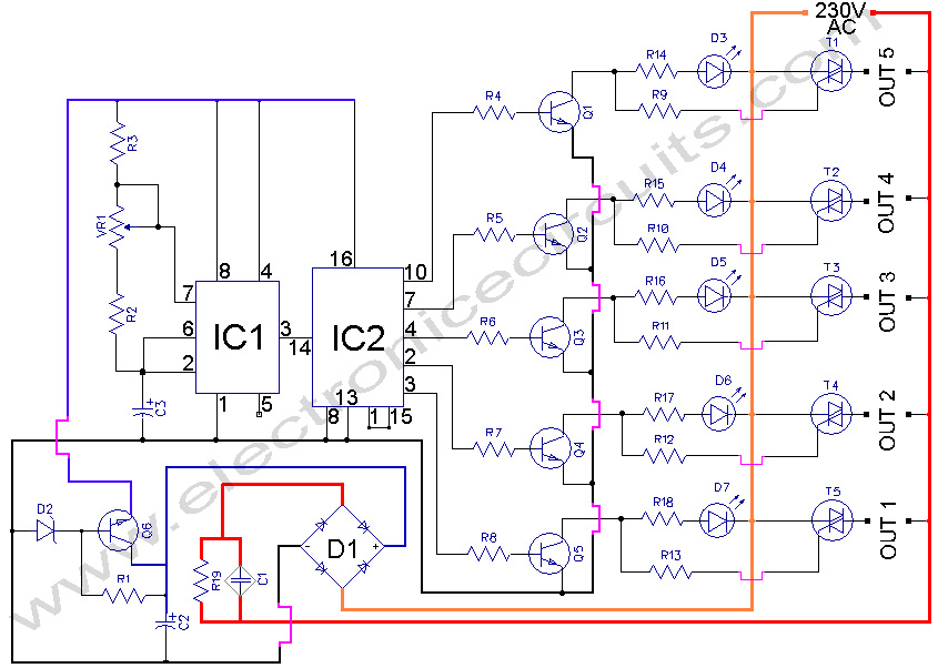
5 WAY AC FLASHER. These types of circuits are commonly used in various ceremonies such as the Wesak festival, Christmas, and weddings. This 5 WAY AC FLASHER circuit. The 5 Way AC Flasher circuit is designed to produce a sequential...
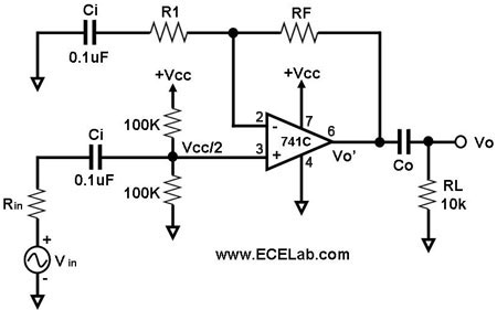
All the capacitors are present to block DC signals; however, the values of capacitance are crucial, and it is necessary to determine the value of Co. Rin denotes the source resistance, which is not an integral part of the...
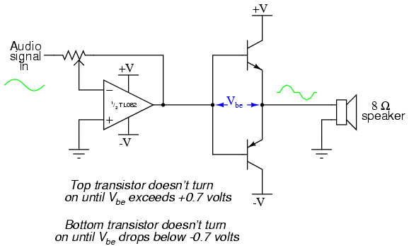
This project is an audio amplifier designed to amplify output signals from small radios, tape players, CD players, or other audio signal sources. For stereo operation, two identical amplifiers must be constructed—one for the left channel and another for...
This controller consists of three pairs of LED sensors arranged in a 3G-bridge configuration. The driver is capable of operating three actuators, with the motors connected in a Delta configuration. The apexes of the delta are linked to the...
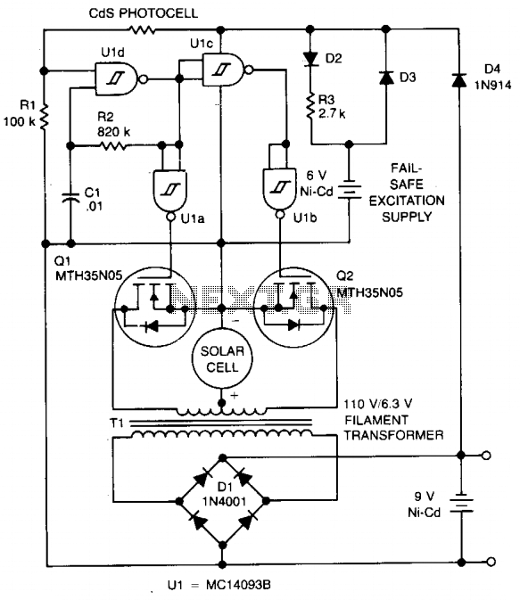
The circuit charges a 9-V battery at approximately 30 mA per input ampere at 0.4 V. U1, a quad Schmitt trigger, operates as an astable multivibrator to drive push-pull MOSFET devices Q1 and Q2. Power for U1 is derived...