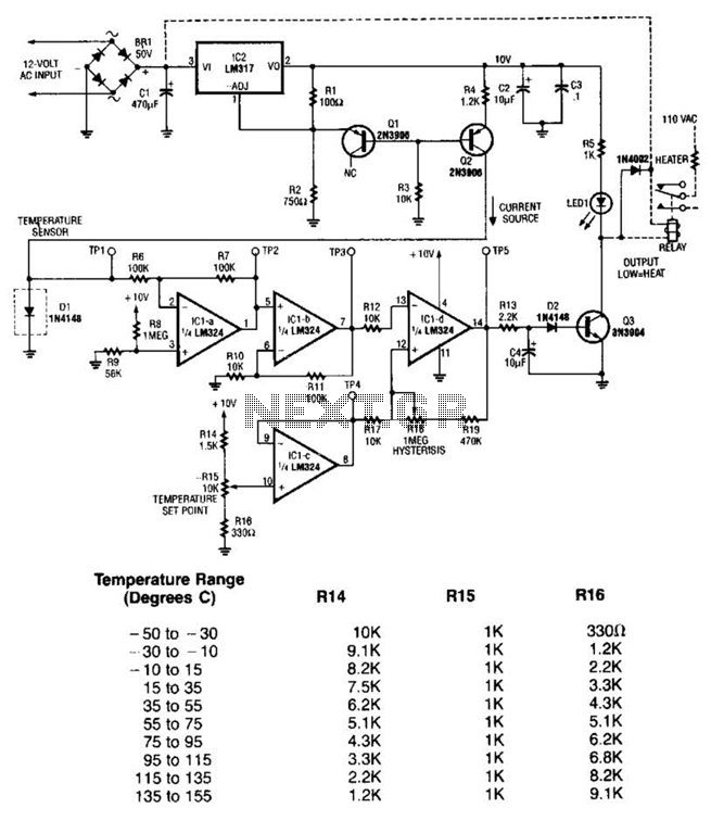
Temperature Sensor Circuit

The LM35 temperature sensor outputs 10 mV/C for each degree Celsius above 0°C. At 20°C, the output voltage is calculated as 20 × 10 = 200 mV. The circuit consumes minimal power. Additionally, the load resistance should not be lower than 5 kΩ, and a supply voltage range of 4 to 20 V can be utilized.
The LM35 temperature sensor is a precision integrated-circuit temperature sensor that provides an analog output voltage proportional to the temperature in degrees Celsius. Specifically, the output voltage increases by 10 mV for each degree Celsius increase in temperature, making it straightforward to interface with analog-to-digital converters (ADCs) or microcontrollers for temperature monitoring applications.
To implement the LM35 in a circuit, it is essential to consider the power supply requirements. The sensor operates effectively with a supply voltage ranging from 4 to 20 V, allowing flexibility in various applications. The power consumption of the LM35 is notably low, which is advantageous for battery-operated devices or low-power systems.
When connecting the LM35 to a load, it is critical to ensure that the load resistance does not fall below 5 kΩ. This specification is important to maintain the accuracy and linearity of the output voltage. If the load resistance is too low, it may draw excessive current, leading to a voltage drop that can distort the sensor's output signal.
In a typical application, the LM35 can be connected in a simple circuit configuration. The output pin of the LM35 should be connected to an ADC input or an operational amplifier for signal conditioning. A bypass capacitor may be added near the power supply pins to filter out any noise. The circuit can also include a resistor in series with the output to limit current and protect the sensor.
Overall, the LM35 is an effective choice for temperature measurement in various electronic applications, including HVAC systems, environmental monitoring, and industrial automation, due to its linear output and ease of integration. The LM35 temperature sensor provides an output of 10 mV/C for every degree Celsius over 0C. At 20C the output voltage is 20 10 = 200 mV. The circuit consumes 00. The load resistance should not be less than 5 kQ. A 4- to 20-V supply can be used.


