
CMOS 4011 Long Delay Timer

In this circuit, the combination of resistor R1 and capacitor C1 creates a time constant that significantly influences the circuit's response to changes in input voltage. The time constant, denoted by τ (tau), is calculated as τ = R1 * C1, where R1 is the resistance in ohms and C1 is the capacitance in farads. This relationship indicates how quickly the capacitor C1 charges and discharges, ultimately affecting the voltage levels at the circuit's output.
When C1 discharges, it does so slowly due to the high resistance value of R1, resulting in a gradual decrease in voltage at the positive lead of the capacitor. This near-zero voltage is crucial for high-impedance inputs, as it minimizes the loading effect on the preceding stages of the circuit. High-impedance inputs are designed to draw minimal current, thus ensuring that the voltage levels remain stable and unaffected by the input stage.
The long time constant provided by R1 and C1 is particularly useful in applications such as analog signal processing, filtering, and timing circuits, where precise voltage levels and timing characteristics are essential. In these scenarios, the circuit can effectively integrate signals over time, allowing for smooth transitions and reducing noise. Furthermore, the choice of R1 and C1 values can be adjusted to tailor the time constant to meet specific design requirements, enabling the circuit to respond appropriately to various signal conditions.A very long time constant is provided by R1 and C1. C1 discharges and the near zero voltage at its positive lead is applied to the high impedance inputs of the.. 🔗 External reference
Related Circuits
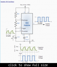
In the following astable multivibrator circuit, some sources state that the duty cycle is represented as d = (R1 + R2) / (R1 + 2 * R2), while other sources provide different information. The astable multivibrator circuit is a type...
The following circuit illustrates a BC547 transistor used in an output relay delay audio amplifier circuit diagram. Features include the immediate disconnection of the speaker when the... The BC547 transistor is a widely utilized NPN bipolar junction transistor, often employed...
The UBA2021 can be utilized as a 600 V lamp controller and half-bridge driver integrated circuit (IC) for high-power applications. It is designed for long-life compact fluorescent lamp (CFL) and tubular fluorescent lamp (TL) applications. The UBA2021 is a versatile...
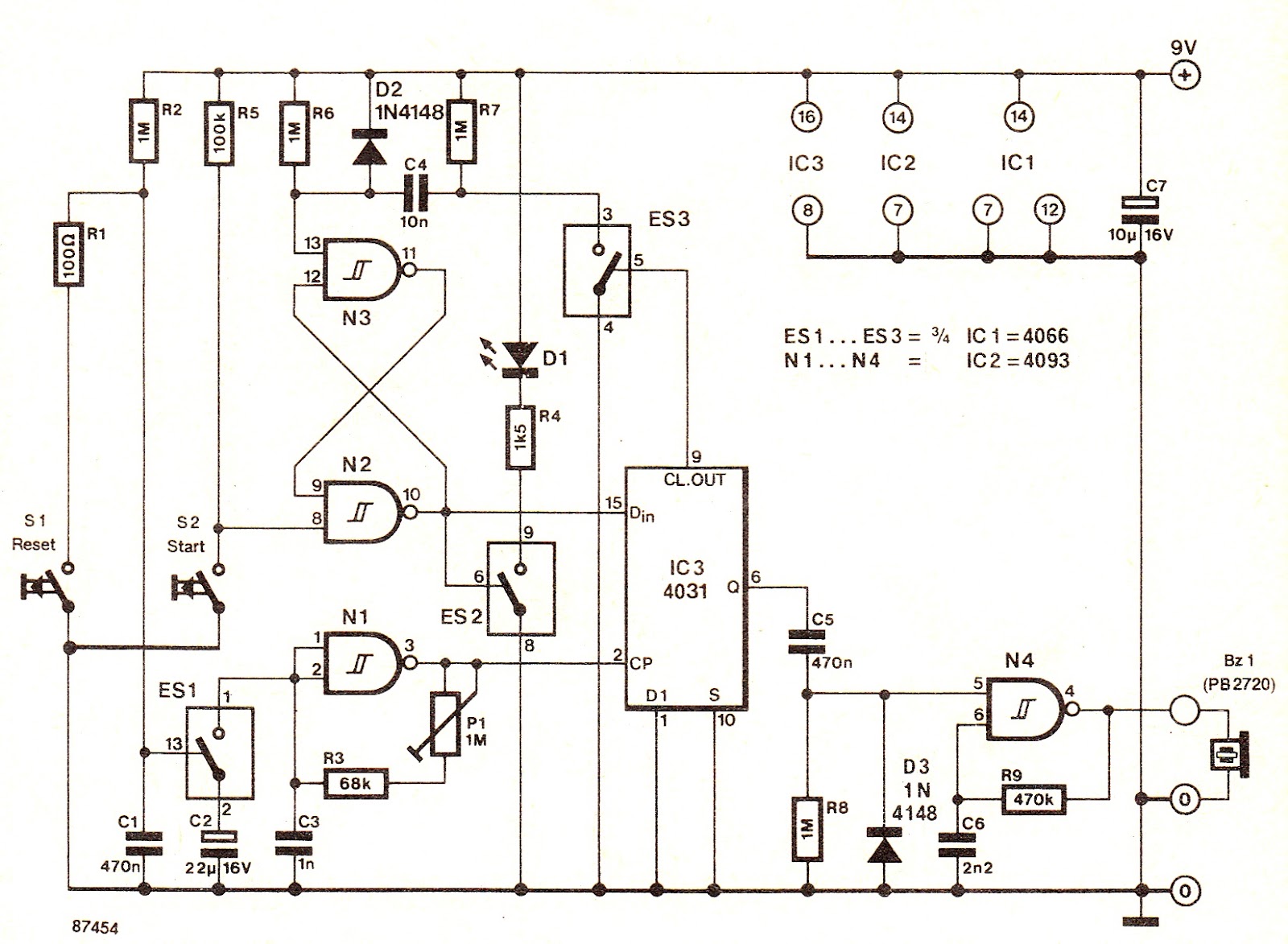
The electronic switch ES1 connects the frequency-determining capacitor to the input of clock oscillator N1. The logic level present at the Dm terminal of the integrated circuit is shifted to output Q at a speed defined by P1, allowing...
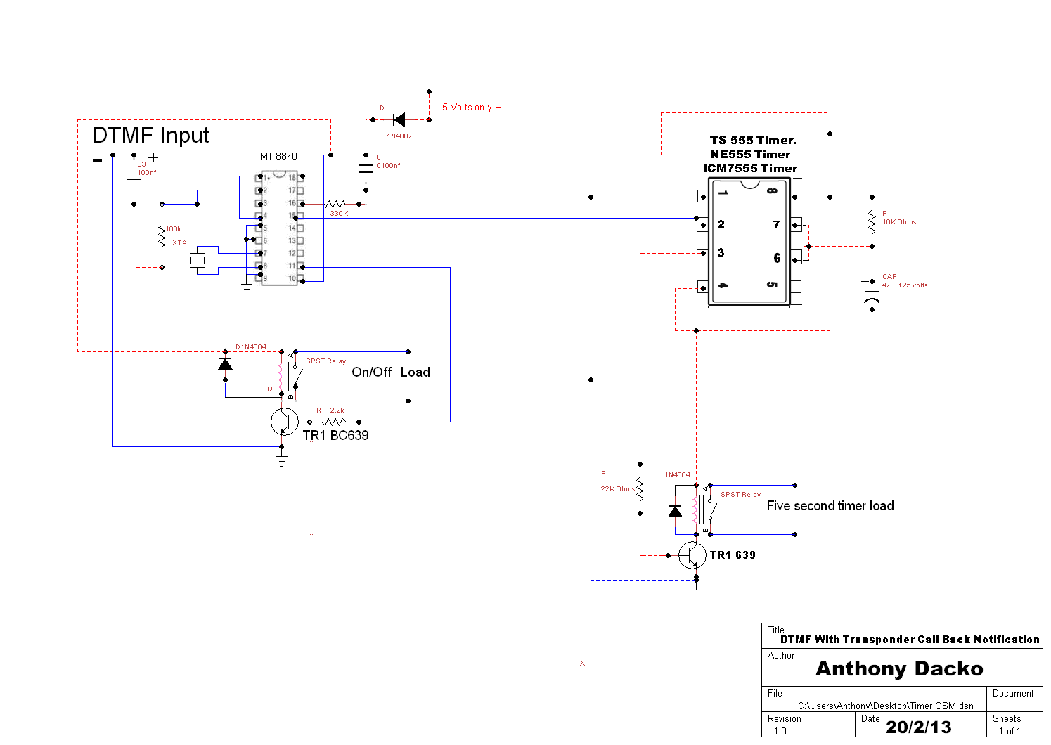
The operation of the circuit is straightforward. When a DTMF tone is sent to the decoder, pin 15 goes high for a brief period, which serves as an effective trigger by supplying a few volts to pin 2 of...
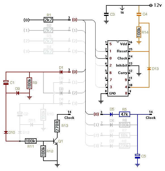
This circuit utilizes a CMOS 4017 decade counter, which begins counting from zero and increments by one each time pin 14 is activated. Upon reaching a count of nine, it resets to zero and starts the counting process again....