
TS555 Timer

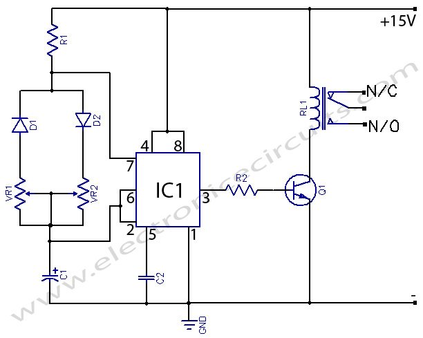
The described circuit utilizes a 555 Timer IC configured in monostable mode, which is triggered by the high signal from the DTMF decoder. The DTMF decoder interprets the tones and sends a signal to pin 15, which, when activated, causes a momentary high voltage at pin 2 of the 555 Timer. This triggers the timer, resulting in the relay being engaged for a predetermined duration, typically set to 5 seconds. The timing can be adjusted by altering the resistance value of R1, allowing for flexibility in the duration of the relay activation.
The relay serves as a switch that can control various devices or send notifications, making this circuit suitable for applications requiring remote signaling or alerts. The use of a modified cell phone as part of the notification system adds an additional layer of functionality, enabling it to call a designated number when the DTMF tone is detected.
The design emphasizes the importance of disabling the answering machine on the receiving phone to ensure that the notification call is not missed. The incorporation of an auto redial feature on the sending phone further enhances reliability, ensuring that the notification is received even if the initial call is not answered.
Overall, this circuit is an effective solution for implementing a notification system based on DTMF tones, providing a simple yet efficient method for remote communication and alerting.How the circuit works is simple when you send a DTMF tone to the decoder the value of pin 15 goes high for a short time this makes an excellent trigger as it supplies a few volts to pin 2 of the 555 Timer this triggers the circuit and turned the relay on for a short time. If you want different times you can experiment with R1 use a Potentiometer or a preset one. 3). Now as soon as Pin 2 on the 555 Timer has a few volts at the Trigger input of pin 2 this will switch the relay over for about 5 seconds if you have set one touch dial or speed dial on your Modified Cell phone then this will call you letting you know it has received valid DTMF tones. 4). It would be best to have this go to a mobile phone if you are still connected to the DTMF Decoder then it would be best to turn your Answer phone off before you make the call to the DTMF Decoder as the sending back phone will call what number is locked in it`s memory.
5). Now most Cell phones have a time delay of 2 or 3 seconds when touch or speed dial is activated this simple design gives you 5 seconds then it switches back waiting for the next time you connect to the DTMF Devise to activate it again. 6). The design is simple to follow it would be a good idea if you set on the transmitting phone the Auto Re-dial you have to turn your answer phone off on your receiving phone just in case it went to answer phone.
7). Now setting the Auto Redial on the sending back mobile phone is good as if you did not disconnect in time it will just phone your again then you just disconnect the incoming call as it has showed on your Screen what call is coming in. 8). In this design I have used a back up Modified cell phone for the Re-sending of the notification signal to me the incoming call does not need to be answered just disconnect the incoming call and you will not be charged for the call.
9). On your receiving Mobile phone put the name in like DTMF Call and it`s number this is letting you know the DTMF Decoder received your command and has sent you a notification signal. In the Schematic below I have designed a simple timer for the following IC`s this will allow a load to be connected till switched off or on the second relay is a Timer for 5 seconds, I designed this to send a notification signal to let me know my DTMF signal was received ok.
🔗 External reference
Related Circuits
This mini metronome provides a linearly scaled output with a range of 40 to 208 beats per minute. The transistors Q1 and Q2 facilitate the linear frequency variation of IC1. The described mini metronome circuit utilizes an integrated circuit (IC1)...
Figure 1 consists of a Programmable Unijunction Transistor (PUT) and an automatic interval timer circuit. In this circuit, the PUT serves as the oscillator. The switch S1 is used to toggle between interval timing and automatic timing modes. When...
The two circuits below illustrate the application of the 555 timer to activate a relay for a specified duration by pressing a momentary normally open (N/O) push button. The circuit on the left can be used for longer time...
To achieve a lower parts count than the two-transistor multivibrators, two LEDs can be alternately flashed using a 555 integrated circuit configured as illustrated in Schematic 2. A combination of a 2.2kΩ and a 47kΩ resistor is used to...
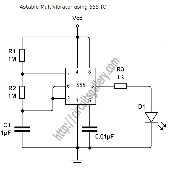
An astable multivibrator can be designed using a 555 timer IC, operational amplifiers, or transistors. The 555 timer IC provides accurate time delays ranging from milliseconds to hours, with the frequency of oscillation adjustable through simple modifications. This is...
555 Timer with On-Off Delay Circuit. This circuit utilizes the commonly available 555 integrated circuit (IC) to create a timer that allows for time adjustment in both on and off states. The 555 timer is a versatile device widely used...