
CMOS 4060 IC For Repeating Interval Timer

The CMOS 4060 IC is a versatile component widely used in timer and oscillator applications due to its high noise immunity and low power consumption. This integrated circuit includes a 14-stage binary ripple counter and an oscillator, which can be configured to generate a variety of timing intervals. The circuit can be designed to produce a stable output frequency by adjusting external components such as resistors and capacitors connected to the timing pins.
In a typical configuration of the repeating interval timer, the CMOS 4060 is connected to an external resistor-capacitor (RC) network. The values of these components determine the frequency of oscillation. The output from the oscillator feeds into the binary counter, which counts the pulses and can be configured to reset after a predetermined count, effectively creating a repeating timer function. The output can be taken from various stages of the counter, allowing for different timing intervals to be achieved depending on the specific application requirements.
To enhance functionality, additional components such as diodes and transistors may be included to drive higher loads or to interface with other logic levels. The circuit can be powered by a standard DC supply, making it suitable for battery-operated devices. Overall, the CMOS 4060-based repeating interval timer circuit is a reliable solution for applications requiring precise timing control.The following circuit shows about CMOS 4060 IC For Repeating Interval Timer Circuit Diagram. Features: Based On The CMOS 4060 IC, 14-bit binary .. 🔗 External reference
Related Circuits
This circuit, enclosed into a small box, is placed in the fridge near the lamp (if any) or the opening. With the door closed the interior of the fridge is in the dark, the photo resistor R2 presents a...
A small circuit that can find a lot of applications for measuring time. It has the capability to inform with a sound signal from the BZ1. At the same time, there exists the possibility to drive an external circuit...
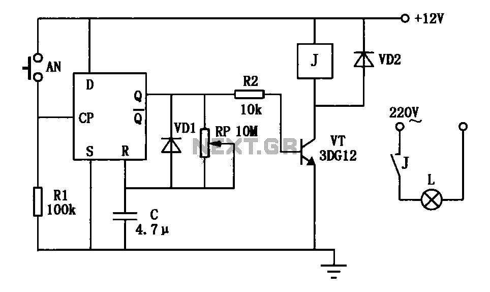
An exposure timer circuit is illustrated using D flip-flops, allowing for timing adjustments between 1 to 30 seconds. The D flip-flop circuit is connected to a one-shot timer. When exposure is required, pressing button AN generates a pulse that...
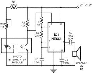
This smoke detector utilizes a 555 timer circuit along with common electronic components. The photo interrupter module serves as the smoke detection element, while the 555 timer is configured in astable mode to function as an audio frequency oscillator,...
This circuit employs a protective resistor R2 along with a feedback resistor R1. Together, these components create a voltage divider that lowers the input voltage amplitude for IC1-a, ensuring that the protective diodes remain inactive. This arrangement enhances the...
This timer was designed primarily to turn off a portable radio after a specific duration. This feature allows users to fall asleep on the beach or in a hammock, with the assurance that the radio will automatically shut off...