
Exposure timer circuit D flip-flops

The exposure timer circuit utilizes D flip-flops to create a versatile timing mechanism. The circuit is designed to allow for a user-defined exposure time that can be set between 1 and 30 seconds. This is achieved through the configuration of the D flip-flops in conjunction with a one-shot timer, which ensures that the timing is accurate and reliable.
When the user requires exposure, pressing button AN generates a pulse that triggers the clock input (CP) of the D flip-flop. This action causes the flip-flop to change its state, which in turn activates the timing sequence. The one-shot timer is responsible for maintaining the output in a steady state for the duration of the selected timing interval. The output of the one-shot timer can be connected to various devices, such as cameras or light sources, to control the exposure duration.
The circuit can be further enhanced by incorporating additional features, such as LED indicators to signal the timing status or adjustable resistors to fine-tune the timing range. The use of D flip-flops ensures that the circuit is stable and can handle multiple timing cycles without degradation in performance. This exposure timer circuit is suitable for applications in photography, scientific experiments, and other scenarios where precise timing is essential.Exposure timer circuit is shown in Figure D flip-flops, timing can be arbitrarily selected within the 1 ~ 30s. Figure D flip-flop circuit connected to a one-shot, when you need the exposure, press the button AN, that is a pulse applied to CP D flip-flop, the circuit into the temporary steady state.
Related Circuits
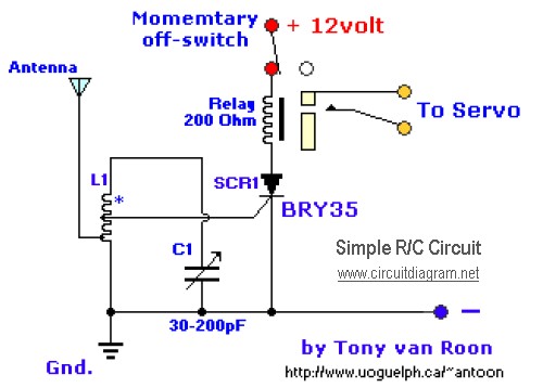
The diagram illustrates a straightforward and efficient receiver designed for activating garage doors, starter motors, alarms, warning systems, and various other applications. The silicon-controlled rectifier (SCR) utilized in this circuit features an exceptionally low trigger current of 30 µA,...
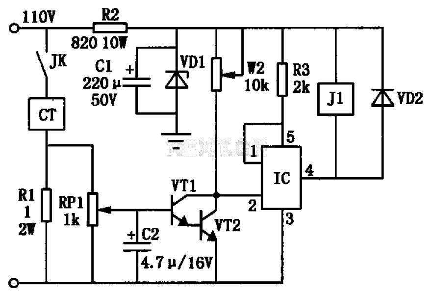
The circuit depicted in the figure utilizes a +24V power supply derived from a 110V power source through an electromagnetic chuck. When the electromagnetic chuck circuit is activated, the contact JK closes, enabling the operation of the magnetic chuck....
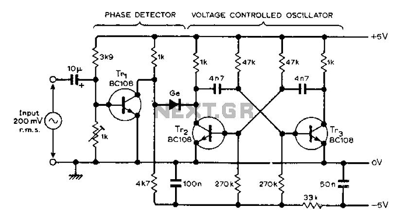
The circuit MVBR utilizes a traditional two-transistor configuration along with other components to create a simple phase-locked loop (PLL). The transistor TR1 and diodes function as a logic gate, activating during half periods of the input waveform of the...
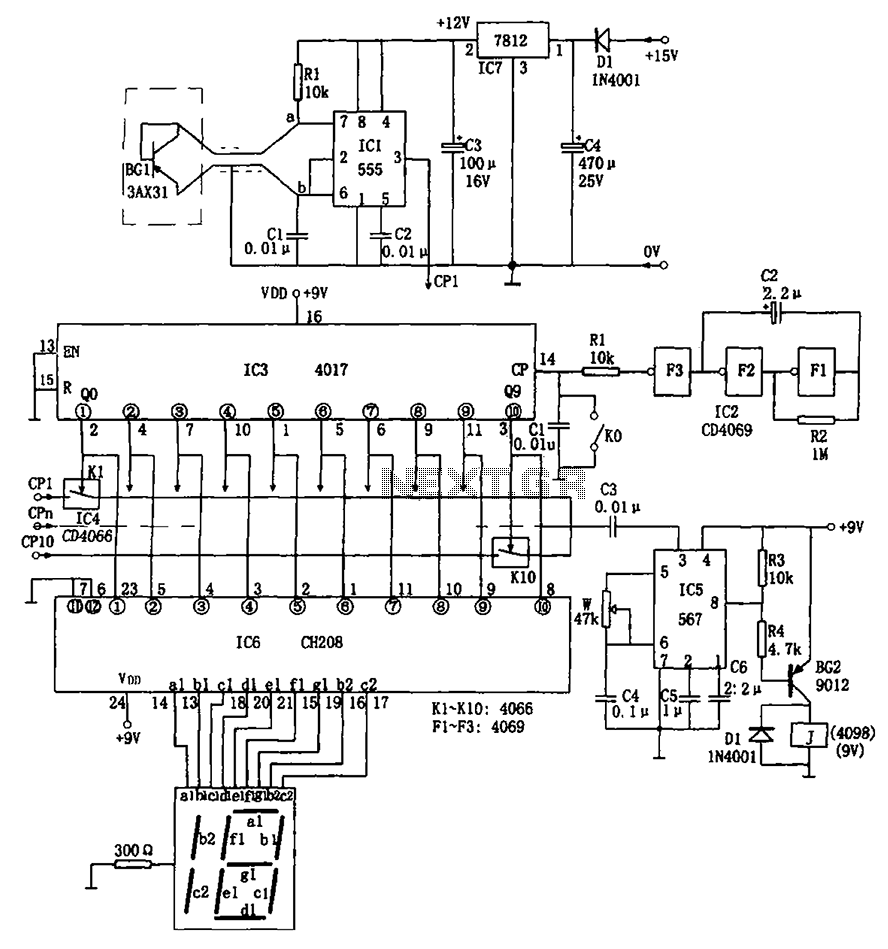
The temperature detection circuit is illustrated in Figure 10. This circuit comprises a temperature sensor, a voltage-to-frequency (V/F) converter, an oscillator, a control program for testing, an alarm system, and a decoding and display circuit. The temperature sensor used...

The ramp voltage from the low-frequency oscillator IC1 modulates IC2, thereby producing a rising and falling tone similar to the wail of police cars. The described circuit utilizes a low-frequency oscillator (IC1) to generate a ramp voltage. This ramp voltage...

This circuit utilizes LM358 operational amplifiers (or any single supply operational amplifier) to generate a pulse-width modulated (PWM) signal. The design was specifically created for a local marine repair company that requested a circuit that is easily repairable and...